Gas diffusion structures and gas diffusion electrodes for polymer electrolyte fuel cells
- Summary
- Abstract
- Description
- Claims
- Application Information
AI Technical Summary
Benefits of technology
Problems solved by technology
Method used
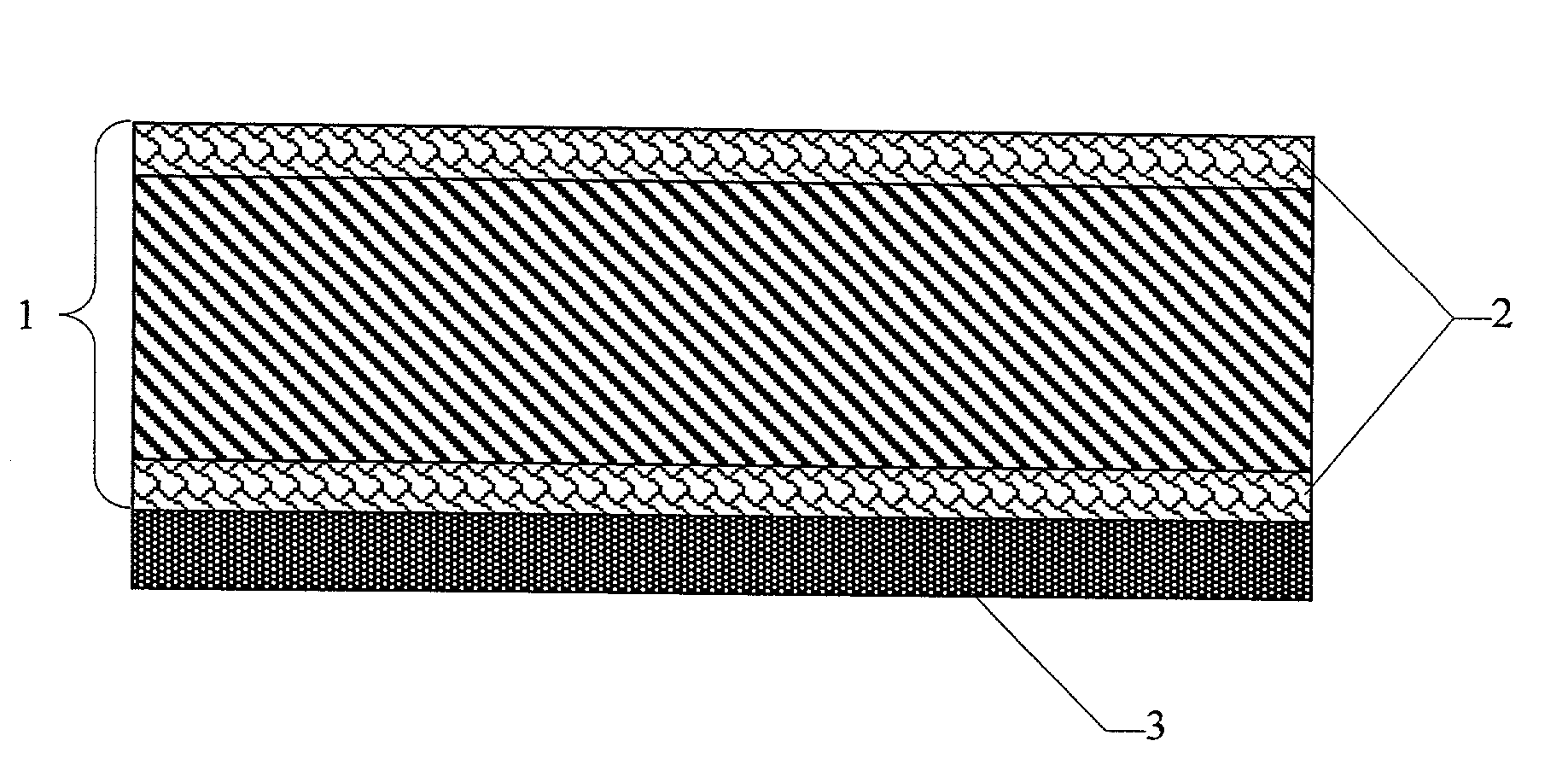
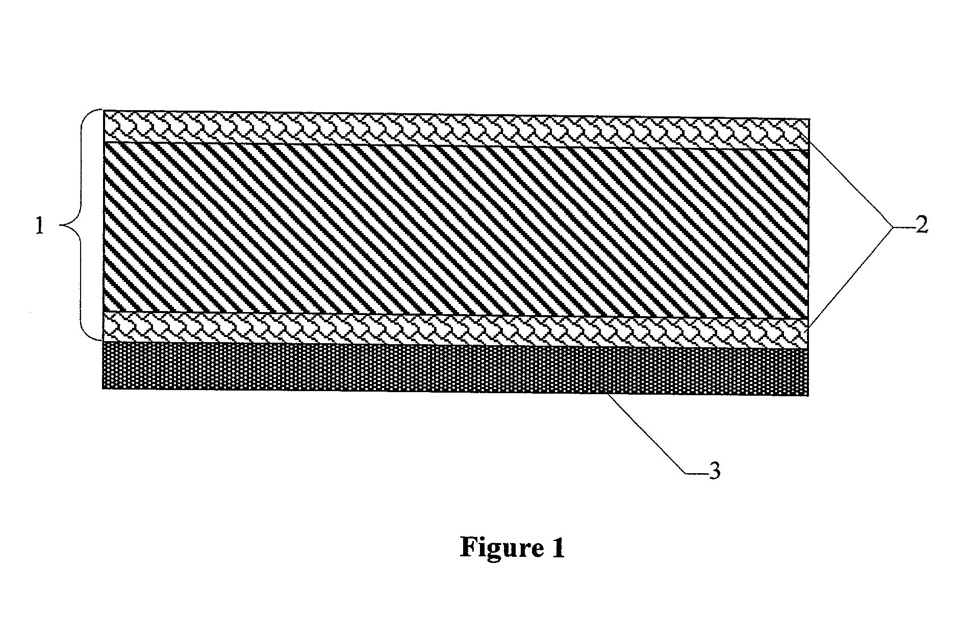
Image

Examples
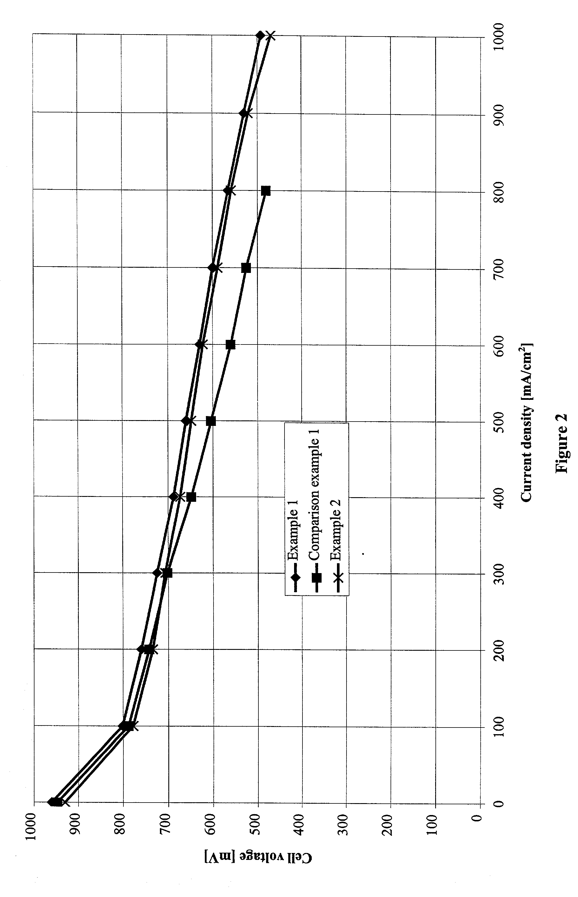
example 1
[0051] Anode gas diffusion structures and cathode gas diffusion structures in accordance with the present invention were manufactured and processed to form complete membrane electrode assemblies.
[0052] The base material used for the gas diffusion structures, as in comparison example 1, was carbon fiber paper with a porosity of 74.1% and a thickness of 200 .mu.m (TGP-H-060 from Toray Inc., Japan). To apply the hydrophobic layers, 5 g of PTFE powder Hostaflon TF1740 (Dyneon Gendorf) with an average particle size of 25 .mu.m was made into a thick paste with 1 g of Shellsol D70 (Shell Co.). The mixture was processed to give a paste-like material and was then applied to one surface of the carbon fiber paper with a doctor blade. Then the coated carbon fiber paper was dried at 100.degree. C. in a circulating air drying cabinet. Then the other face was coated using the same procedure.
[0053] To melt the applied PTFE, the carbon fiber paper was sintered for about 15 minutes in a box kiln at 3...
example 2
[0061] In a second set of trials, the hydrophobic layers were incorporated in the carbon support by an alternative process. Instead of coating the carbon support with a paste of a hydrophobic polymer, PTFE films were laid on the surfaces of the carbon support.
[0062] Again the carbon support used was the carbon fiber paper used in example 1 with a porosity of 74.1% and a thickness of 200 .mu.m (TGP-H-060 from Toray Inc., Japan). A 0.030 mm thick film of porous ePTFE (density: 0.38 g / cm.sup.3, TETRATEX from W. L. Gore & Associates) was laid on each face and the entire multilayered structure was fastened between two stainless steel plates (thickness 1 mm). The package prepared in this way was sintered for about 15 minutes at 340 to 350.degree. C. in a box kiln. Then the stainless steel plates were removed. The carbon fiber papers obtained in this way had a surface loading of 17 g PTFE / m.sup.2 after treatment. These carbon fiber papers were used in the following as substrates for anode ...
PUM
| Property | Measurement | Unit |
|---|---|---|
| Fraction | aaaaa | aaaaa |
| Linear density | aaaaa | aaaaa |
| Pressure | aaaaa | aaaaa |
Abstract
Description
Claims
Application Information
 - R&D
- Intellectual Property
- Life Sciences
- Materials
- Tech Scout
- Unparalleled Data Quality
- Higher Quality Content
- 60% Fewer Hallucinations
Browse by: Latest US Patents, China's latest patents, Technical Efficacy Thesaurus, Application Domain, Technology Topic, Popular Technical Reports.
© 2025 PatSnap. All rights reserved.Legal|Privacy policy|Modern Slavery Act Transparency Statement|Sitemap|About US| Contact US: help@patsnap.com