
Internal combustion engine with combustion heater

a technology of combustion heater and internal combustion engine, which is applied in combustion-air/fuel-air treatment, lighting and heating apparatus, electric control, etc., can solve the problems of low heat generation amount of internal combustion engine, low temperature of exhaust gas, and harmful gas components in burnt gas emitted from combustion heater

Inactive Publication Date: 2002-03-14
TOYOTA JIDOSHA KK
View PDF0 Cites 5 Cited by
  • Summary
  • Abstract
  • Description
  • Claims
  • Application Information

AI Technical Summary

Benefits of technology

This approach effectively elevates the temperature of the exhaust gas purifying device, enhances engine warm-up acceleration, and improves emission quality by ensuring the catalyst reaches activation temperature more quickly, thereby reducing emissions and improving engine performance.

Problems solved by technology

However, in the combustion heater, since the combustion is conducted by utilizing the part of the fuel for the internal combustion engine, there are cases where the burnt gas emitted from the combustion heater contains harmful gas components like the emission of the internal combustion engine.
However, since these exhaust gas purifying devices are activated so that the harmful gas components contained in the exhaust gas may be purified when the catalyst bed temperature exceeds a predetermined level, in order to positively purify the burnt gas from the combustion heater and the exhaust gas from the internal combustion engine, it is necessary to keep the exhaust gas purifying devices at the activation temperature or more.
However, in the case where the internal combustion engine is a diesel engine, a heat generation amount of the internal combustion engine tends to be small in a low load operational region, and the exhaust gas temperature is likely to be low.
Accordingly, it is difficult to keep the exhaust gas purifying device at the activation temperature or more only by the exhaust gas of the internal combustion engine.
However, since the temperature of the exhaust gas to be discharged from the above-described combustion heater is lowered by the heat exchange with the heating air in the heat exchange portion, there is a problem in that it takes long time to elevate the temperature of the exhaust gas purifying device up to the activation temperature, and the exhaust emission would become worse in the meantime.
In this case, if the amount of the intake air of the internal combustion engine is decreased by the intake throttle valve, even if the amount of the gas discharged from the combustion heater is small, it is impossible to sufficiently elevate the temperature of the intake air and to reduce the amount of fuel consumption for the operation of the combustion heater.
The reason for this is that, in the internal combustion engine with a combustion heater, it is expected that the pressure of the intake air supercharged by the supercharger is considerably high by the pressure of the exhaust gas, and in such a case, if the second burnt gas passage is communicated, the intake passage and the exhaust passage are in communication with each other through the combustion heater so that the amount of the intake air passing through the combustion heater is excessively increased to degrade the ignitability of the combustion heater.
On the other hand, in the internal combustion engine provided with the supercharger in the intake passage, in extinguishment, i.e., in the inoperative condition of the combustion heater, if the second burnt gas passage is communicated to thereby communicate the intake passage and the exhaust passage with each other, a part of the intake air supercharged by the supercharger is bypassed around the internal combustion engine to flow into the exhaust passage, resulting in degradation of the supercharging effect by the supercharger.

Method used


Image

  • Internal combustion engine with combustion heater
  • Internal combustion engine with combustion heater
  • Internal combustion engine with combustion heater

Examples


embodiment 1

[0129] Embodiment 1

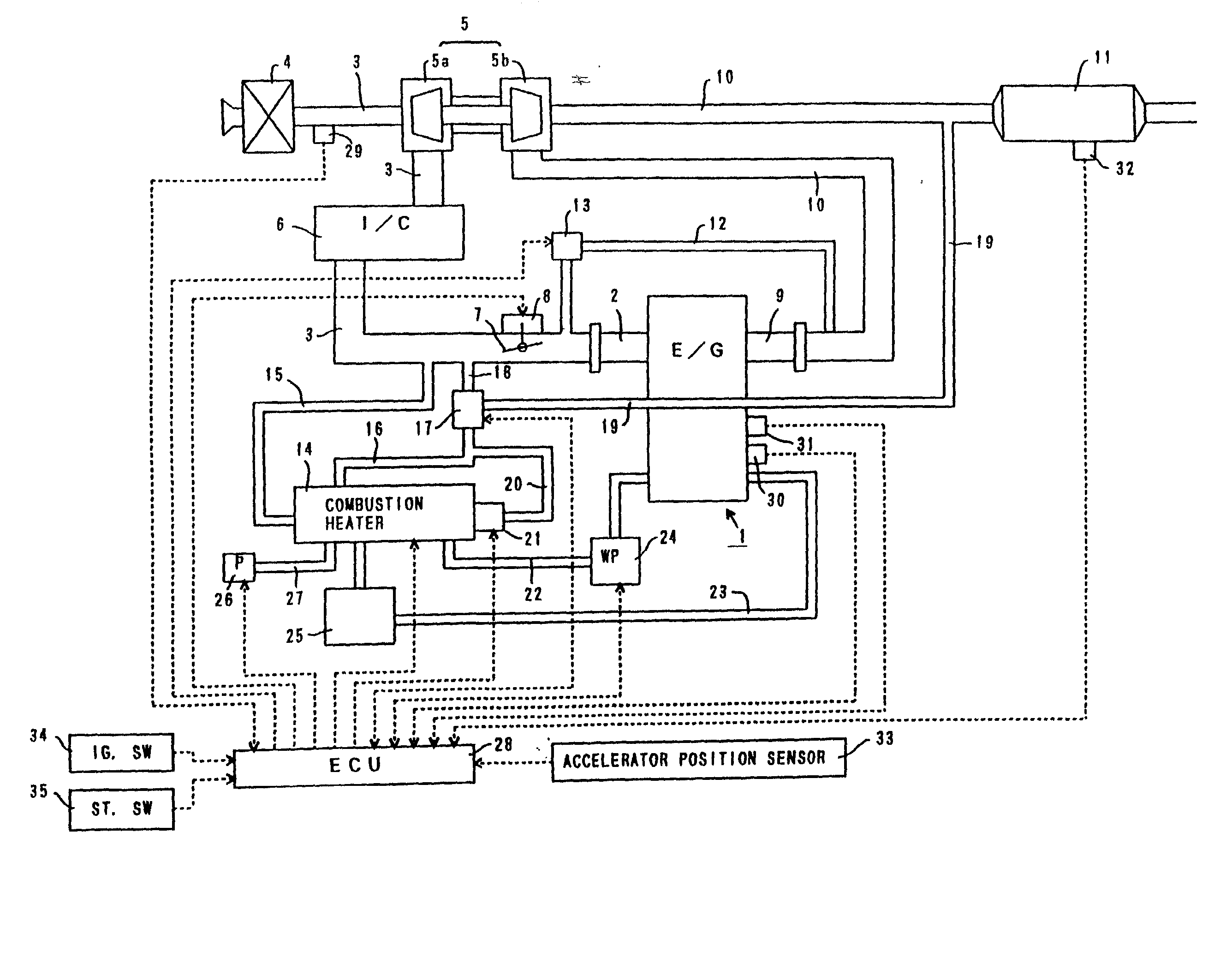
[0130] FIG. 1 is a view showing a schematic structure of an internal combustion engine with a combustion heater according to the present invention.

[0131] In FIG. 1, the internal combustion engine 1 is a water-cooled sleeve interior injection type diesel engine provided with a fuel injection valve for injecting fuel directly into a combustion chamber of each cylinder.

[0132] An intake-manifold 2 is connected to the internal combustion engine 1. Each branch pipe of the intake manifold 2 is in communication with the combustion chamber of each cylinder through an intake port (not shown). The above-described intake manifold 2 is connected to an intake pipe 3. The intake pipe 3 is connected to an air cleaner box 4 containing an air filter.

[0133] A compressor housing 5a of a centrifugal supercharger (turbo charger) 5 is provided in the midway of the intake pipe 3. A compressor wheel is rotatably supported within the compressor housing 5a. A rotary shaft of this compressor...

embodiment 2

[0232] Embodiment 2

[0233] An internal combustion engine with a combustion heater in accordance with a second embodiment of the present invention will now be described with reference to the drawings. In this case, the structure that is different from that of the above-described first embodiment will now be described and the explanation of the similar structure will be omitted.

[0234] FIG. 9 is a schematic view of the internal combustion engine with the combustion heater in accordance with the embodiment.

[0235] In this embodiment, the first burnt gas discharging port 145 of the combustion heater 14 is in direct communication with a portion upstream of the intake throttle valve 7 and downstream of the intake air introducing passage 15 in the intake pipe 3 through the first burnt gas discharging passage 16.

[0236] The second burnt gas discharging port 147 of the combustion heater 14 is in communication with a portion downstream of the intake throttle valve 7 in the intake pipe 3 through t...

embodiment 3

[0255] Embodiment 3

[0256] An internal combustion engine with a combustion heater in accordance with a third embodiment of the present invention will now be described with reference to the drawings. In this case, the structure that is different from that of the above-described first embodiment will now be described and the explanation of the similar structure will be omitted.

[0257] FIG. 10 is a schematic view of the internal combustion engine with the combustion heater in accordance with the embodiment.

[0258] In this embodiment, the first burnt gas discharging port 145 of the combustion heater 14 is in direct communication with a portion upstream of the intake throttle valve 7 and downstream of the intake air introducing passage 15 in the intake pipe 3 through the first burnt gas discharging passage 16.

[0259] The second burnt gas discharging port 147 of the combustion heater 14 is in communication with a portion downstream of the turbine housing 5b in the exhaust pipe 10 and upstream...


PUM


Abstract

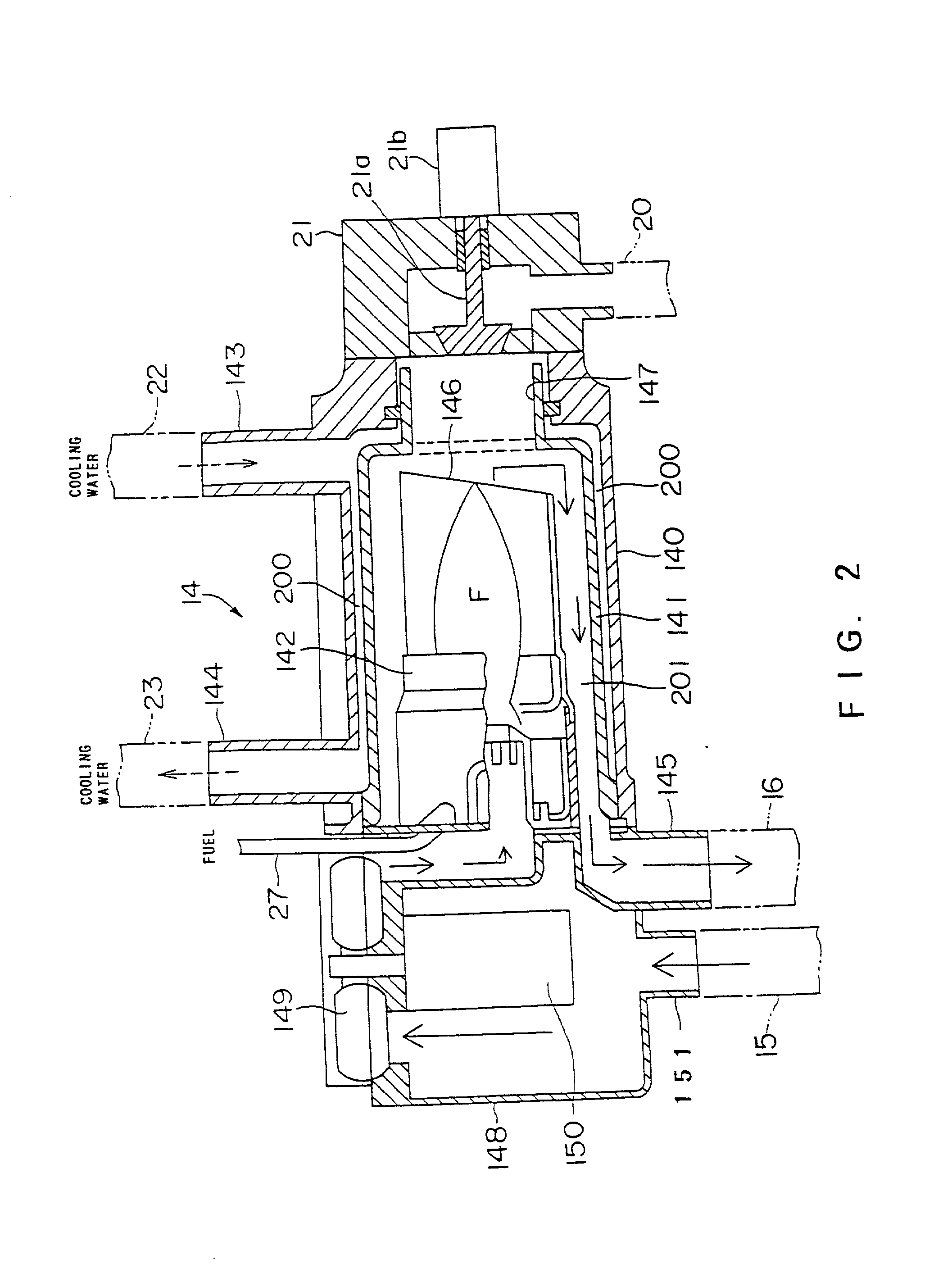
In an internal combustion engine with a combustion heater for elevating a temperature of an engine related element, an object of the present invention is to provide a technique that may effectively performs temperature elevation of an exhaust gas purifying device. In order to attain this object, according to the present invention, the internal combustion engine having an exhaust gas purifying catalyst provided in an exhaust passage of the internal combustion engine, and a combustion heater comprising a combustion chamber and a heat exchange portion for transmitting to an engine related element heat held by burnt gas that has been burnt in said combustion chamber, characterized by including a first burnt gas discharging portion for discharging from the combustion heater the burnt gas which has passed through the heat exhcange portion, a second burnt gas discharging portion for discharging from the combustion heater the burnt gas which has not yet passed through the heat exchange portion, and a burnt gas passage controlling unit for supplying at least one of burnt gas discharged by the first burnt gas discharging portion and burnt gas discharged by the second burnt gas discharging portion to the exhaust gas purifying catalyst.

Description

[0001] This is a division of application Ser. No. 09 / 470,125 filed Dec. 22, 1999.[0002] 1. Field of the Invention[0003] The present invention relates to an internal combustion engine provided with a combustion heater for elevating a temperature of an engine related element such as cooling water or intake air.[0004] 2. Description of the Related Art[0005] In an internal combustion engine to be mounted on an automotive vehicle or the like, in particular, an internal combustion engine such as a diesel engine in which a heat quantity is likely to be small, a technique to additionally provide a combustion heater for the purpose of acceleration of warming up the internal combustion engine or enhancement of a passenger room heating device in a cold state.[0006] The above-described combustion heater is provided with a combustion chamber which is independent of the internal combustion engine. Furthermore, the combustion heater is provided with a heat exchange portion composed of a water path...

Claims


Application Information

Patent Timeline
Patent Type & Authority Applications(United States)
IPC IPC(8): B60H1/03F01N3/20F02M31/07F01N3/24F01N3/30F01N3/36F01N9/00F02B29/00F02M25/07F02M31/08F02M31/16F23N1/02
CPCF01N3/2006F01N3/2033F01N3/306F01N9/00F01N2240/14F02B29/00F02M25/0707F02M25/0718F02M31/163F23N1/022F23N2035/04F23N2041/14Y02T10/146Y02T10/126Y02T10/26Y02T10/47F02M26/05F02M26/15F23N2235/04F23N2241/14Y02T10/12Y02T10/40
Inventor SUZUKI, MAKOTO
Owner TOYOTA JIDOSHA KK
Learn More