Charger configured to charge battery pack of power tool

a technology of power tools and chargers, which is applied in the direction of electric variable regulation, process and machine control, instruments, etc., can solve the problems of insufficient ventilation increased unexpected temperature of the charging circuit, and possible ingress of dust into the housing, so as to reduce the amount of dust remaining in the housing, the effect of sufficiently ventilated and airflow ra

Active Publication Date: 2020-09-03
MAKITA CORP
View PDF0 Cites 1 Cited by
  • Summary
  • Abstract
  • Description
  • Claims
  • Application Information

AI Technical Summary

Benefits of technology

[0004]Accordingly, the present specification provides a technique that is capable of reducing buildup of dust in a charging circuit in a charger in which an inside of a housing is ventilated by a blower.
[0006]In order to prevent dust from intruding through the intake port, it is preferable to make the intake holes of the intake port small. If each of the intake holes is made excessively small, however, a flow rate of air in the intake port decreases, and the inside of the housing cannot be sufficiently ventilated. In this regard, as a result of examining the intake holes of various shapes, it was identified that even when the intake holes have a same area as each other, an amount of dust passing through an intake hole with a smaller inscribed circle is less than those of other intake holes. This also applies to the exhaust holes of the exhaust port. That is, even when the exhaust holes have a same area as each other, an amount of dust passing through an exhaust hole with a smaller inscribed circle is less than those of other exhaust holes. Based on the above identifications, in the above-described charger, each inscribed circle of the plurality of intake holes is smaller than any of inscribed circles of the plurality of exhaust holes. According to such a configuration, the intrusion of dust from the intake port into the housing is reduced, and more dust that has intruded into the housing can be discharged from the exhaust port. As a result, the amount of dust remaining in the housing is reduced, and the buildup of dust in the charging circuit can be reduced.

Problems solved by technology

In a charger that ventilates its housing by a blower, dust may possibly intrude into the housing from its intake port.
If the dust that has intruded into the housing is deposited on a substrate or electrical component(s) of a charging circuit, heat dissipation of the charging circuit is inhibited.
In this case, there may be a case where a temperature of the charging circuit increases unexpectedly.
If each of the intake holes is made excessively small, however, a flow rate of air in the intake port decreases, and the inside of the housing cannot be sufficiently ventilated.

Method used


Image

  • Charger configured to charge battery pack of power tool
  • Charger configured to charge battery pack of power tool
  • Charger configured to charge battery pack of power tool

Examples


embodiments

[0030]A charger 10 of an embodiment will be described with reference to the drawings. As shown in FIG. 1, the charger 10 is an electric device configured to charge a battery pack 100. The battery pack 100 is a power source for a power tool (not shown) and is detachably attached to the power tool. The charger 10 of the present embodiment is configured to charge the battery pack 100 in a state of being detached from the power tool. In other embodiments, however, the charger 10 may be configured to charge the battery pack 100 while it is attached to the power tool.

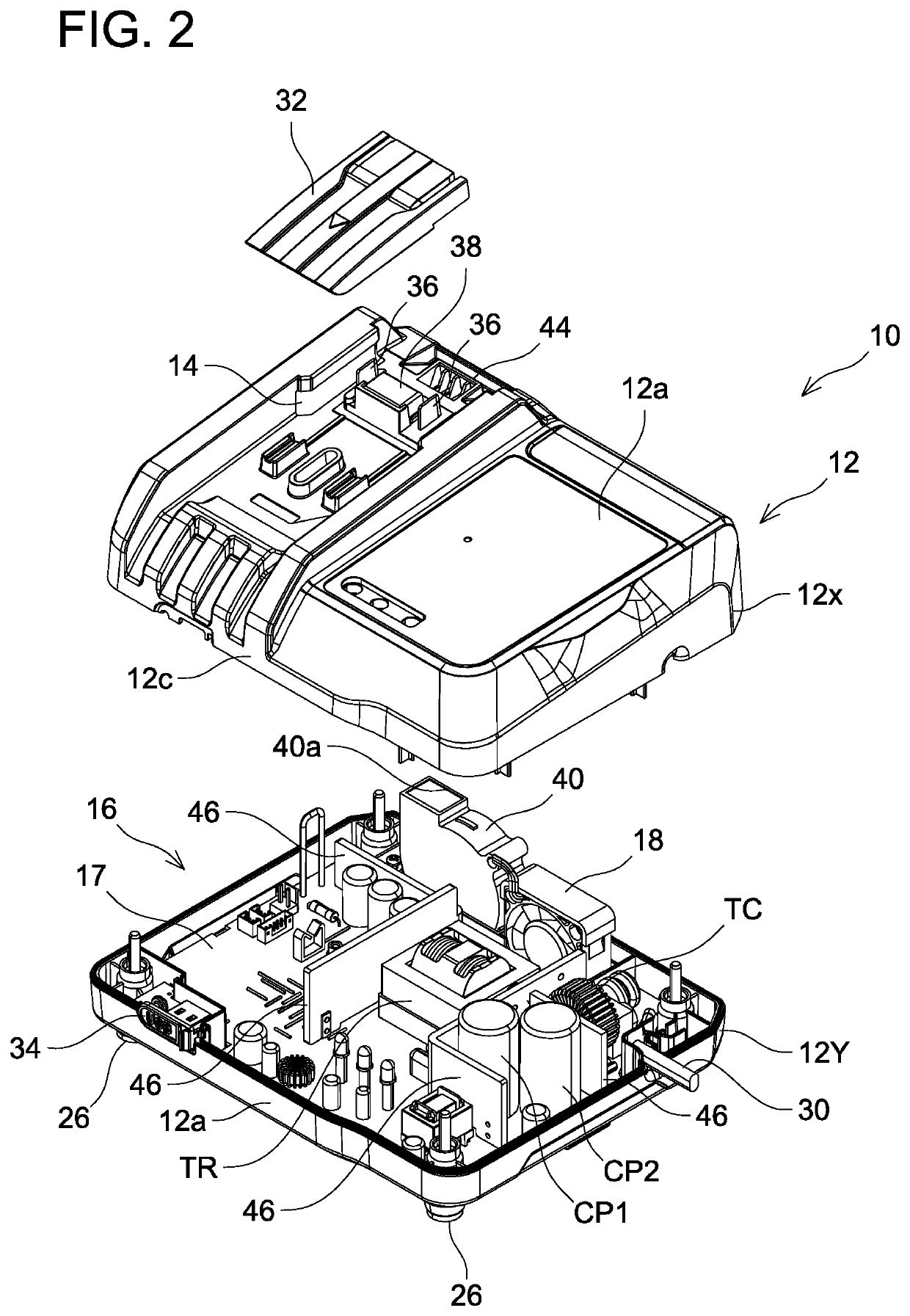
[0031]As shown in FIGS. 1-5, the charger 10 comprises a housing 12, a battery interface 14, a charging circuit 16, and a blower 18. The battery interface 14 is provided to the housing 12 and is configured to detachably receive the battery pack 100. The charging circuit 16 is provided in the housing 12 and is configured to supply charging power to the battery pack 100 attached to the battery interface 14. The blower 18 is conf...


PUM


Abstract

A charger configured to charge a battery pack of a power tool, and the charger include: a housing having an intake port and an exhaust port; a battery interface included on the housing and configured to removably receive a battery pack, a charging circuit in the housing and configured to supply charging power to the battery pack attached to the battery interface; and a blower configured to introduce air from the intake port into the housing and discharge the air from the exhaust port to the outside of the housing. The intake port includes a plurality of intake holes formed in the housing, and the exhaust port includes a plurality of exhaust holes formed in the housing. Each inscribed circle of the plurality of intake holes is smaller than any of inscribed circles of the plurality of exhaust holes.

Description

TECHNICAL FIELD[0001]The technology disclosed herein relates to a charger configured to charge a battery pack of a power tool.BACKGROUND ART[0002]Japanese Patent Application Publication No. 2016-149841 discloses a charger configured to charge a battery pack of a power tool. The charger includes a housing having an intake port and an exhaust port, a battery interface provided to the housing, a charging circuit configured to supply charging power to the battery pack attached to the battery interface, and a blower configured to introduce air from the intake port into the housing and discharge air from the exhaust port to an outside of the housing. According to such a configuration, since an inside of the housing is forcibly ventilated by the blower, a temperature rise of the charging circuit is reduced.SUMMARY OF INVENTION[0003]In a charger that ventilates its housing by a blower, dust may possibly intrude into the housing from its intake port. If the dust that has intruded into the ho...

Claims


Application Information

Patent Timeline
Patent Type & Authority Applications(United States)
IPC IPC(8): H02J7/00H02M3/335
CPCH02M3/33569H02J7/0045B25F5/02H02J2207/20H02J7/00H02J7/0042H02J7/02B25F5/008H02M3/33571Y02E60/10
Inventor TAGA, HIDEYUKI
Owner MAKITA CORP
Why Eureka
Try Eureka