
Position detection method and position detector, exposure method and exposure apparatus, and device and device manufacturing method

Inactive Publication Date: 2002-02-07
NIKON CORP
View PDF0 Cites 25 Cited by
  • Summary
  • Abstract
  • Description
  • Claims
  • Application Information

AI Technical Summary

Benefits of technology

[0022] A second object of the present invention is to provide an exposure method and exposure apparatus that can transfer a predetermined pattern onto a substrate with high accuracy.
[0023] A third object of the present invention is to provide a device on which fine patterns are accurately formed.
[0024] A fourth object of the present invention is to provide a manufacturing method of manufacturing a device on which fine patterns are accurately formed.

Problems solved by technology

The accuracy of the arrangement coordinate position determination of shot areas determined under the above premise suffices to achieve conventionally required exposure accuracy, but does not suffice for the increase of integration degree in recent years.
However, since prior art 2 requires a huge computation volume for fuzzy inference, a long period of time is required to determine the arrangement coordinate positions of shot regions, and this makes it difficult to improve the throughput of exposure.
However, the use thereof causes the whole exposure apparatus to be large and complicated.
Therefore, it is not guaranteed that the error distribution of the positions of a plurality of alignment marks as elements of a sample set determined by the conventional method appropriately reflects the error distribution of positions of all alignment marks.
This method presupposes that only few isolated shots exist, and that those alignment marks cause the decrease of alignment accuracy for all shot regions.
Therefore, exclusion of the measured position information of alignment marks contained in an isolated shot area may result in an alignment accuracy decrease.
However, there have been no proposals concerning a method for selecting a sample set from the entire set of alignment marks formed on a substrate so as to perform statistically valid position control and alignment on the basis of the position measurement results of alignment marks in the sample set.
Furthermore, although it is not appropriate to exclude alignment marks in descending order of position error amounts in order to reduce the number of sample alignment marks and alignment measurement time, there have been no proposals concerning a method for reducing the number of sample alignment marks while maintaining alignment accuracy.

Method used


Image

  • Position detection method and position detector, exposure method and exposure apparatus, and device and device manufacturing method
  • Position detection method and position detector, exposure method and exposure apparatus, and device and device manufacturing method
  • Position detection method and position detector, exposure method and exposure apparatus, and device and device manufacturing method

Examples


Embodiment Construction

[0122] An embodiment of the present invention will be described hereinafter with reference to FIGS. 1 to 12.

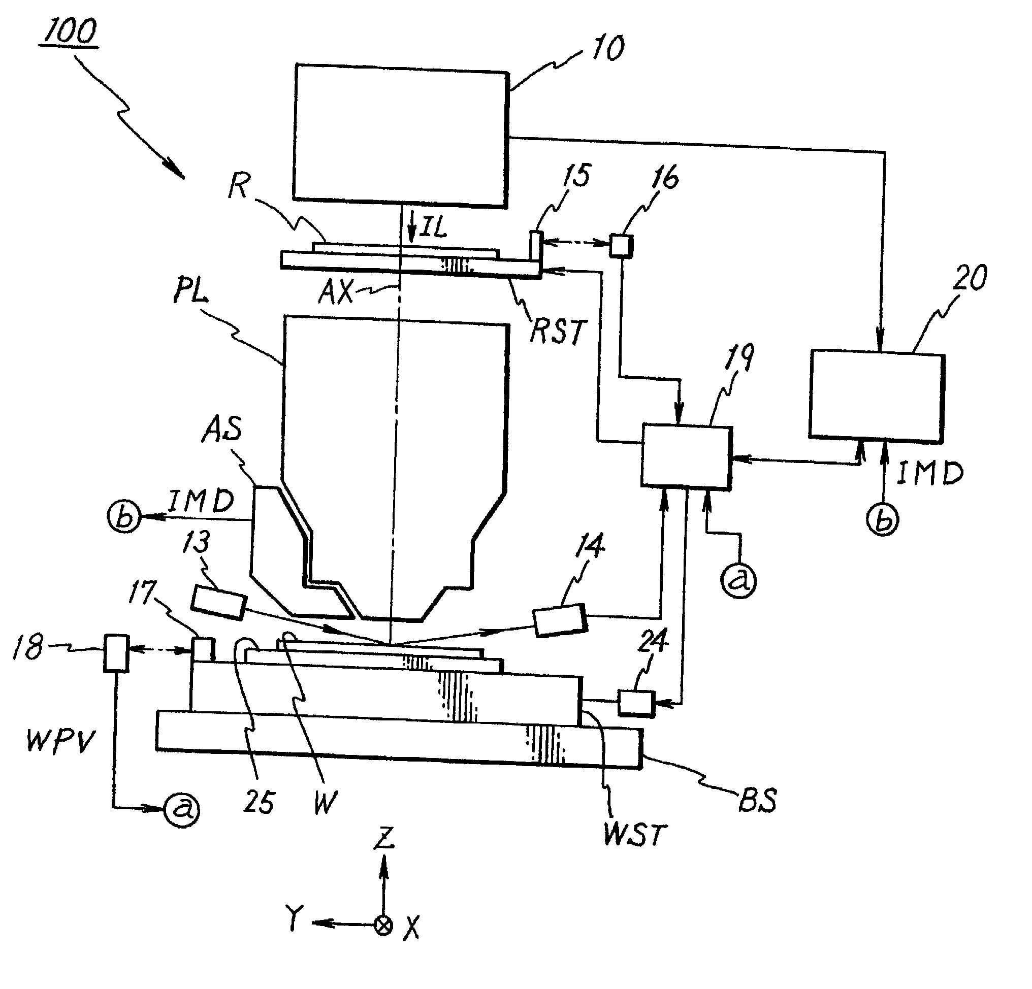
[0123] FIG. 1 shows a schematic arrangement of an exposure apparatus 100 according to an embodiment of the present invention. This exposure apparatus 100 is a step-and-scan projection exposure apparatus. The exposure apparatus 100 comprises an illumination system 10, a reticle stage RST for holding a reticle R as a mask, a projection optical system PL, a wafer stage WST on which a wafer W as a substrate (object) is placed, an alignment microscope AS as an image pickup unit, a main control system 20 for systematically controlling the overall apparatus, and the like.

[0124] The illumination system 10 includes a light source, an illuminance uniforming optical system comprising a fly-eye lens as an optical integrator, a relay lens, a variable ND filter, a reticle blind, a dichroic mirror, and the like (none of them are shown). The arrangement of such illumination system is disclose...


PUM


Abstract

A parameter calculation unit statistically calculates the estimations and their certainty of a predetermined number of parameters, which uniquely specify any position on an object, for each of a plurality of measured sample sets on the basis of position information of marks composing the sample set. A valid value calculation unit calculates statistically valid values of the predetermined number of parameters on the basis of groups of the estimations and their certainty of the predetermined number of parameters for the respective sample sets. Furthermore, an evaluation unit statistically evaluates if the number of marks composing a sample set can be reduced. If it is determined that the number of marks can be reduced, the parameter calculation unit calculates values of the predetermined number of parameters by using a new sample set having reduced number of marks. Using the values of the predetermined number of parameters calculated in this manner, the position of any area on the object can be accurately detected.

Description

[0001] This is a continuation of International Application PCT / JP00 / 00855, with an international filing date of Feb. 16, 2000, the entire content of which being hereby incorporated herein by reference.[0002] 1. Field of the Invention[0003] The present invention relates to a position detection method and position detector, an exposure method and exposure apparatus, and a device and device manufacturing method and, more particularly, to a position detection method and position detector for obtaining arrangement information of divided areas on an object, an exposure method and exposure apparatus using the position detection method, and a device manufactured using the exposure method and a manufacturing method thereof.[0004] 2. Description of the Related Art[0005] In a lithography process for making semiconductor devices, liquid crystal display devices, and the like, an exposure apparatus which transfers a pattern formed on a mask or reticle (to be generally referred to as a "reticle" h...

Claims


Application Information

Patent Timeline
IPC IPC(8): G03F9/00
CPCG03F9/7003G03F9/7046G03F9/7092G01B11/00
Inventor YOSHIDA, KOUJI
Owner NIKON CORP
Learn More