
Method of uniformly coating a substrate

a technology of uniform coating and substrate, applied in the field of uniform coating of substrate, can solve the problems of increasing the viscosity of the polymer solution, affecting the uniformity of the resulting film, and non-uniform thickness, so as to reduce the cost, reduce the thickness of the solution layer, and reduce the amount of polymer solution

Inactive Publication Date: 2002-01-10
ASML HLDG NV
View PDF62 Cites 10 Cited by
  • Summary
  • Abstract
  • Description
  • Claims
  • Application Information

AI Technical Summary

Benefits of technology

[0006] It is an object of the invention to provide a method of and an apparatus for improving the thickness uniformity of a polymer solution applied to a surface of a substrate such as a semiconductor wafer.
[0007] It is a further object of the invention to improve the consumption of polymer solutions such as photoresist pre-polymer solutions used in the coating of substrates.
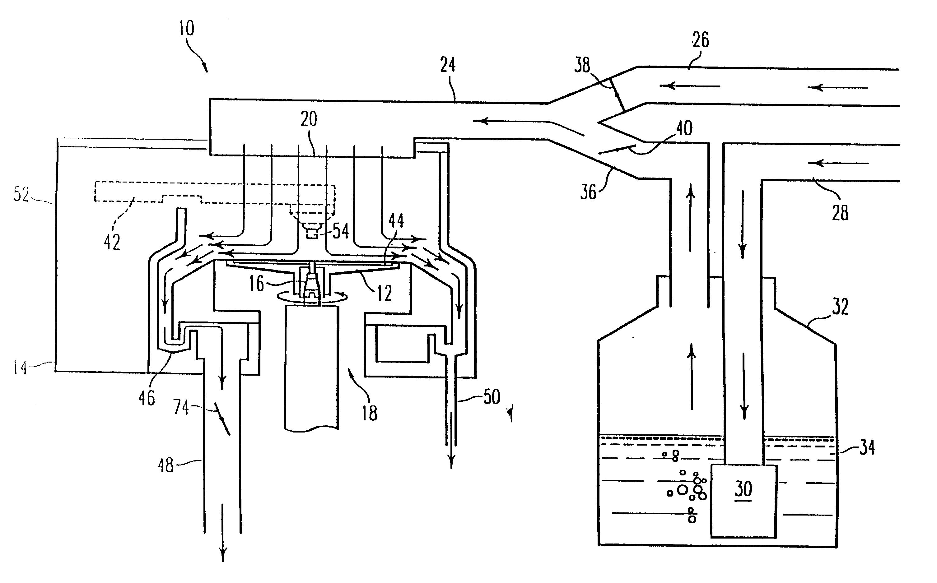
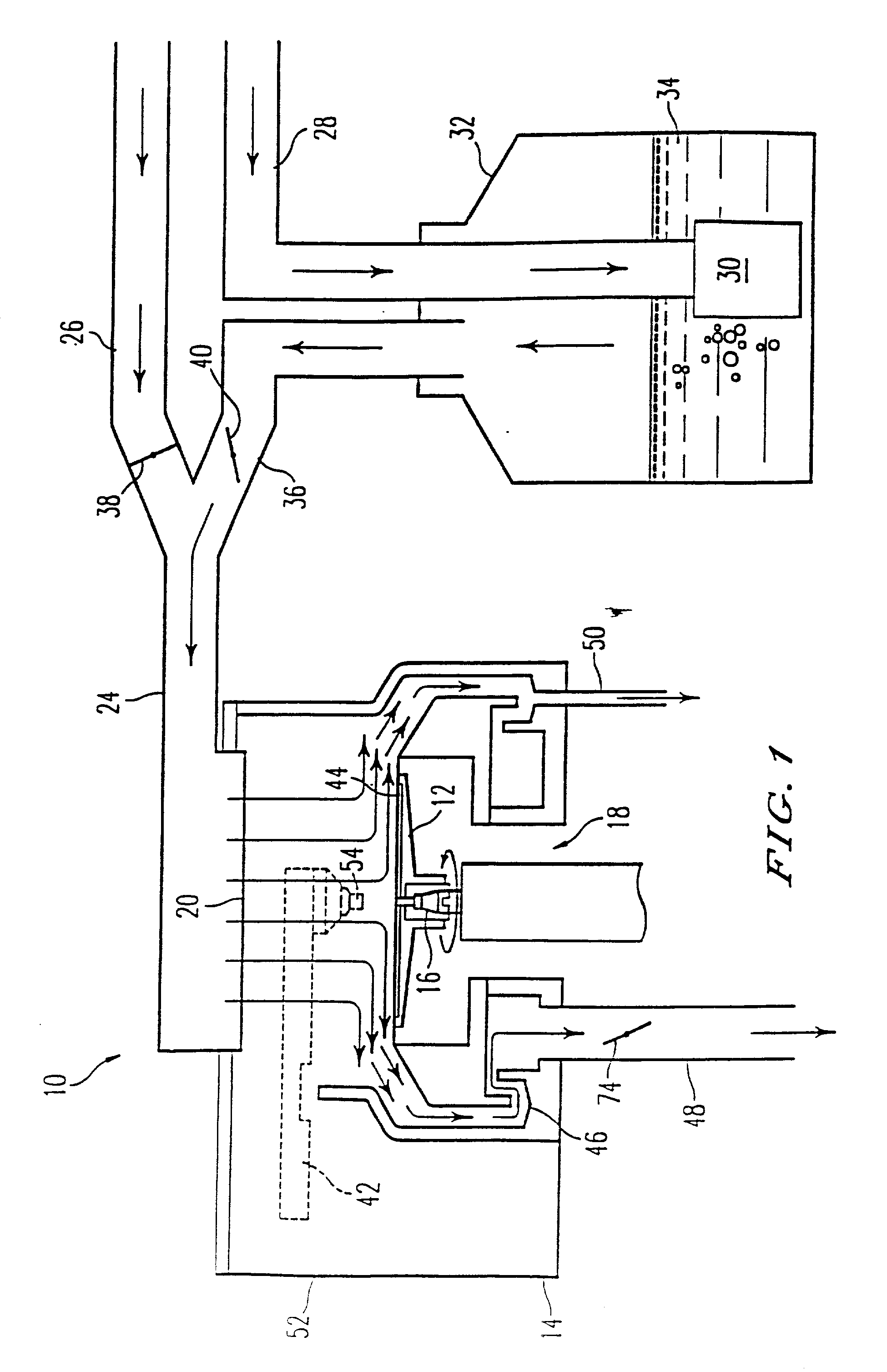
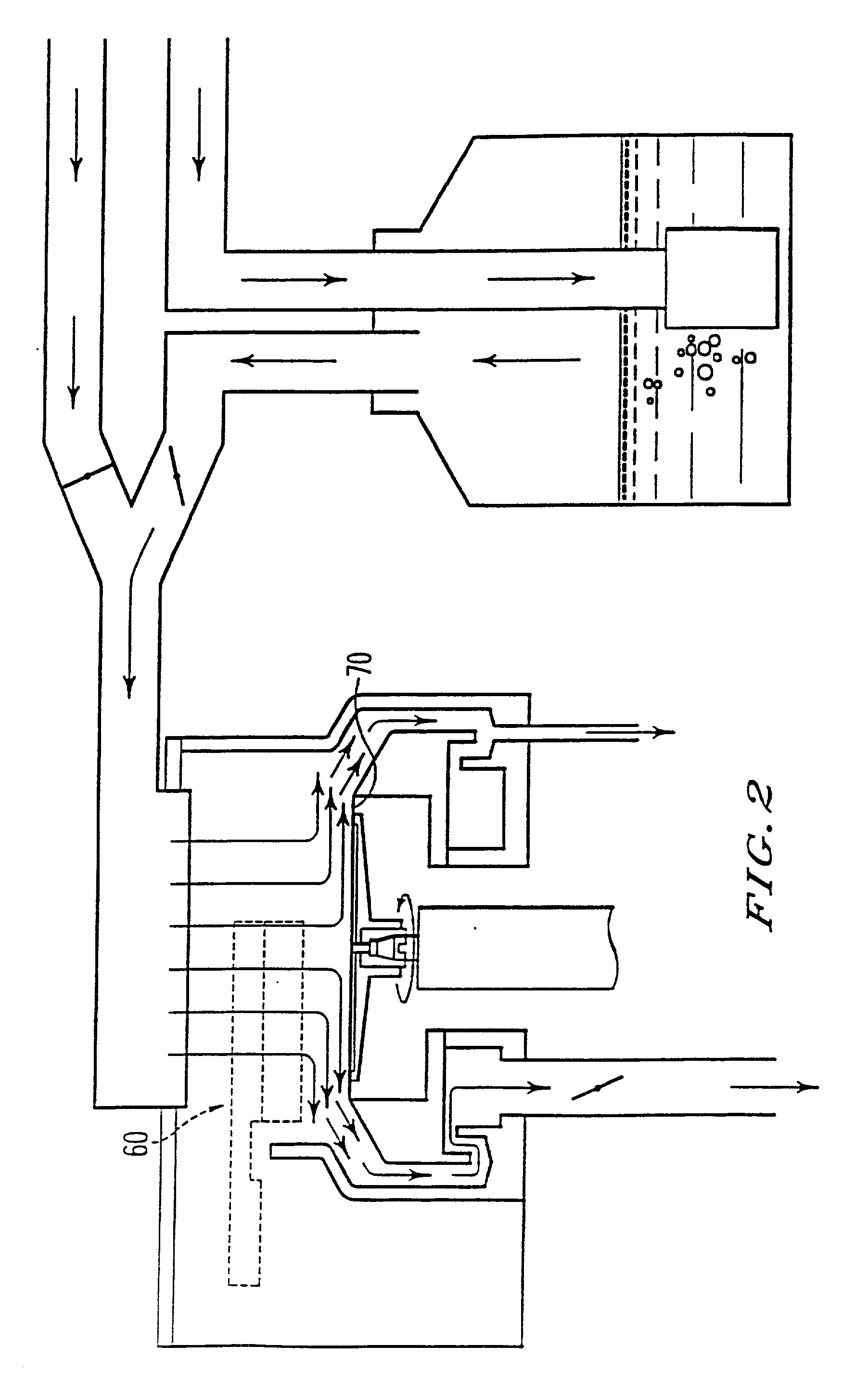
[0033] As will become clearer from the discussion which follows below it is desirable to conduct the coating process of the semiconductor wafer in a housing or chamber which allows the atmosphere in the chamber to be at least partially saturated with solvent molecules. This has the advantage of improving the cast film wetability by establishing a monolayer coating of solvent on the surfaces of the substrate. Furthermore by controlling the concentration of solvent in the gas within the chamber, thickness uniformity of the polymer solution film on the substrate can be improved. This will be the case whether spin-cast films, spray-coated films or any other similar coating method is adopted.
[0035] Problems are also encountered when insufficient coating solution is used. When attempts are made to reduce costs by minimizing the amount of the coating solution applied to the surface of the substrate during spin-casting, non-uniformities are created due to the low solvent volume. Evaporation of the solvent during the coating process results in various defects and irregularities. Similarly, in spray-coated films, solvent tends to evaporate during the application, thus increasing viscosity and inhibiting the levelling of the resulting film, again resulting in thickness non-uniformities.
[0047] Solvent vapor pressure can be determined precisely by using an isoteniscope. Alternatively, by passing inert gas through a sample of the solution and measuring the amount of solvent removed as a function of time gravimetrically, the vapor pressure can be determined precisely. The solvent partial pressure in the gas supplied by the conduit 36 can be adjusted, optimally to correspond to the equilibrium vapor pressure created by the solvent in the polymer solution. This ensures that the rate at which solvent evaporates from the deposited film or coating is equal to the rate at which the solvent is absorbed by the film from the gaseous environment.
[0049] By continuously exhausting the solvent-bearing gas or humid air via the exhaust 48, humidity and solvent partial pressure in the housing can readily be adjusted during the coating process to ensure a uniform solution layer thickness on the semiconductor wafer surface. Similarly the effects of premature evaporation of solvent from the polymer solution deposited on the wafer 44 can be eliminated. This allows less polymer solution to be used, thereby reducing costs.

Problems solved by technology

The solvent in the photoresist tends to evaporate during application, increasing the viscosity of the polymer solution and inhibiting the leveling of the resulting film.
This produces thickness non-uniformities.

Method used


Image

  • Method of uniformly coating a substrate
  • Method of uniformly coating a substrate
  • Method of uniformly coating a substrate

Examples


Embodiment Construction

[0050] A coating apparatus according to the invention and sized appropriately for 200 mm diameter wafers was assembled and installed in a wafer track machine. In-situ air pressure, air temperature, relative humidity and solvent concentration measurements were performed during the wafer processing. Ethyl lactate was used as the casting solvent for the photoresist. Solvent concentration within the process chamber was varied between 0-40% of the saturated value.

[0051] FIGS. 3a and 3b demonstrate results obtained by practicing a method according to the invention. As shown in FIGS. 3a and 3b, final film thickness can be varied by controlling solvent evaporation independent of the spin speed. In the limit of zero solvent flow rate, the evaporation rate is maximum, yielding the thickest film due to coupled nature of convective and evaporative mass transfer mechanisms. As the solvent flow rate is increased evaporation rate is reduced allowing resist film to continue thinning via convective ...


PUM

PropertyMeasurementUnit
temperatureaaaaaaaaaa
diameteraaaaaaaaaa
thicknessaaaaaaaaaa

Abstract

A method of and an apparatus for coating a substrate with a polymer solution to produce a film of uniform thickness, includes mounting the substrate inside an enclosed housing and passing a control gas, which may be a solvent vapor-bearing gas into the housing through an inlet. The polymer solution is deposited onto the surface of the substrate in the housing and the substrate is then spun. The control gas and any solvent vapor and particulate contaminants suspended in the control gas are exhausted from the housing through an outlet and the solvent vapor concentration is controlled by controlling the temperature of the housing and the solvent from which the solvent vapor-bearing gas is produced. Instead the concentration can be controlled by mixing gases having different solvent concentrations. The humidity of the gas may also be controlled.

Description

[0001] This application claims the benefit of provisional U.S. patent application Ser. No. 60 / 185,818 filed Feb. 29, 2000. This application is also a continuation-in-part of U.S. patent application Ser. No. 09 / 391,964 filed Sep. 8, 1999 which is a continuation of U.S. patent application Ser. No. 08 / 876,273 filed Jun. 16, 1997 (now U.S. Pat. No. 5,954,878) which is a divisional of U.S. patent application Ser. No. 08 / 566,227 filed Dec. 1, 1997 (now U.S. Pat. No. 5,670,210) which is a continuation-in-part of U.S. patent application Ser. No. 08 / 330,045 filed Oct. 27, 1994 (now abandoned), all applications of which are incorporated herein by reference in their entirety.[0002] The manufacture of integrated circuits involves the transfer of geometric shapes on a mask to the surface of a semiconductor wafer. Thereafter the semiconductor wafer corresponding to the geometric shapes or corresponding to the areas between the geometric shapes is etched away. The transfer of the shapes from the m...

Claims


Application Information

Patent Timeline
Patent Type & Authority Applications(United States)
IPC IPC(8): B05C5/02B05D1/00B05D1/26B05D3/04G03F1/16H01L21/00
CPCB05C5/0208B05C5/0254B05D1/005B05D1/265B05D3/0486H01L21/6715
Inventor GURER, EMIRZHONG, TOMLEWELLEN, JOHNLEE, EDMANDAL, ROBERT P.GRAMBOW, JAMES C.BETTES, TED C.SAUER, DONALD R.WARD, EDMOND R.
Owner ASML HLDG NV
Learn More