
Battery and process for preparing the same

a battery and process technology, applied in the field of batteries and process for preparing the same, can solve the problems of increasing the short-circuit current that cannot be controlled in a conventional lithium secondary battery, increasing the temperature of the battery further, and avoiding exothermic reactions, etc., to achieve supplement low electronic conductivity, low volume specific resistance, and low electronic conductivity

Inactive Publication Date: 2001-06-28
MITSUBISHI ELECTRIC CORP
View PDF0 Cites 49 Cited by
  • Summary
  • Abstract
  • Description
  • Claims
  • Application Information

AI Technical Summary

Benefits of technology

[0057] Therefore, when the battery is formed by using this electrode, there are advantageous effects that safety of the battery is remarkably improved and is maintained even in an unusual situation such as short-circuit in severe conditions, reversed charge or overcharge.

Problems solved by technology

However, when the safety valve is operated, water in air may invade into the battery to react with lithium in the negative electrode and there is a fear of an exothermic reaction.
Since the conventional lithium secondary battery has the structure mentioned above, there exist the following problems.
At occurrence of short-circuit and temperature rise inside the lithium secondary battery, increase of the short-circuit current can not be controlled in a conventional lithium secondary battery.
But in case of using a solid electrolyte or a gel electrolyte instead of these separators or if a lithium battery is prepared without using separator, there is no component for decreasing short-circuit due to softening and melting of the separator, and an alternative safety component is necessary.
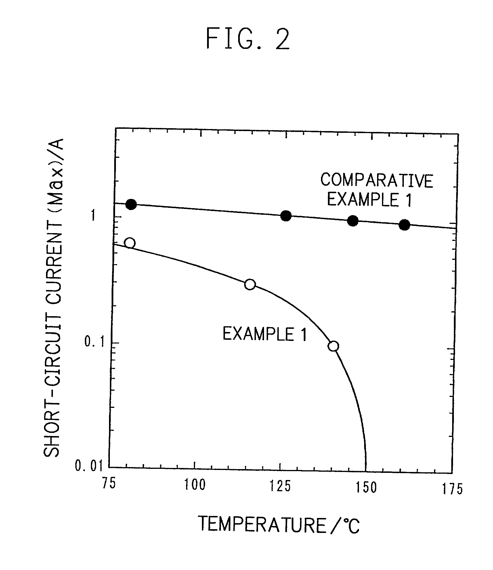
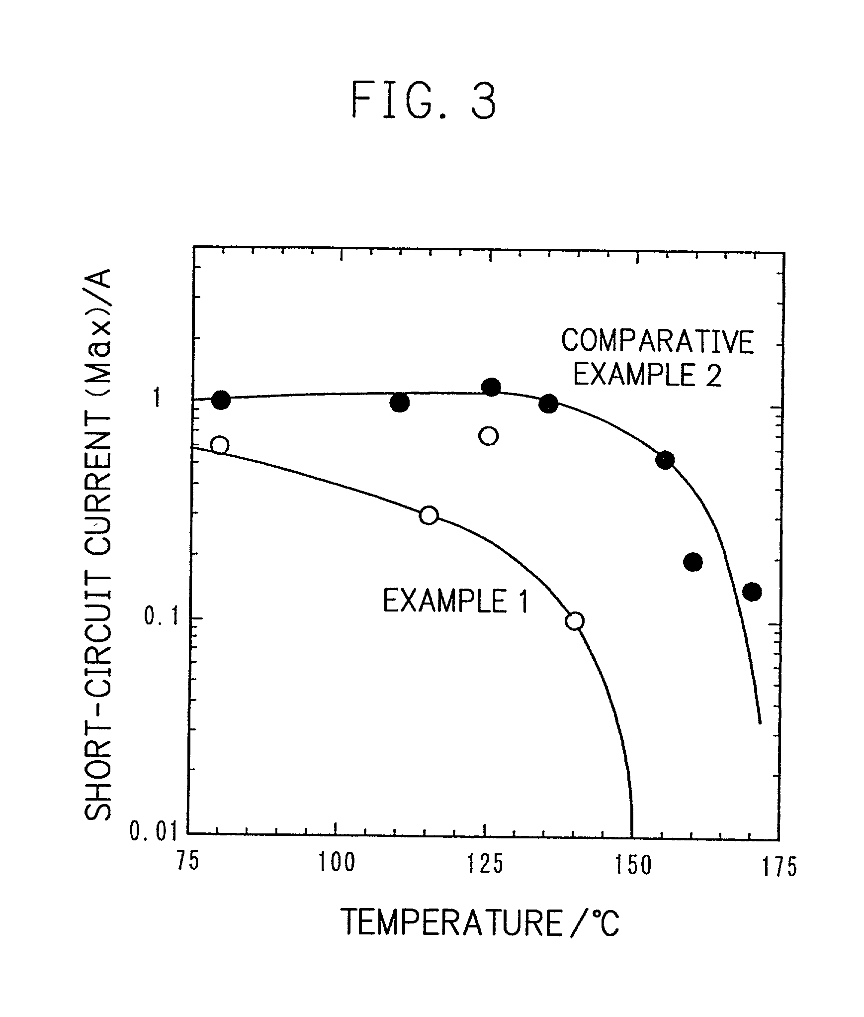
As mentioned above, such a battery has a problem that when a temperature of the battery increases due to internal short-circuit or the like, there is no component for decreasing short-circuit current, and large short-circuit current is generated, and thus temperature of the battery further increases due to generation of heat, leading to a further increase of short-circuit current.

Method used


Image

  • Battery and process for preparing the same
  • Battery and process for preparing the same
  • Battery and process for preparing the same

Examples


example 2

[0126] The ratio of the electronically conductive material in preparation of the positive electrode in Example 1 was varied. FIG. 4 illustrates the relationship between a ratio of the electronically conductive material and volume specific resistance of the electrode and relationship between a ratio of the electronically conductive material and discharging capacitance. Specifically, FIG. 4 illustrates relationship between a ratio of the electronically conductive material to 100 parts by weight of the total solid content of the electrode (herein the positive electrode) of the battery and volume specific resistance of the electrode ((a) in the figure), and relationship between a ratio of the electronically conductive material to 100 parts by weight of the total solid content of the electrode (herein the positive electrode) of the battery and discharging capacitance ((b) in the figure).

[0127] As shown in the figure, when an amount of the electronically conductive material is at most 0.5...

example 3

[0129] Particle size of the electronically conductive material in preparation of the positive electrode in Example 1 was varied. FIG. 5 illustrates the relationship between the particle size of the electronically conductive material and the resistance of the electrode ((a) in the figure) and the relationship between the particle size of the electronically conductive material and the discharging capacitance ((b) in the figure).

[0130] When the particle size of the electronically conductive material is at most 0.05 .mu.m, a filling ratio of the electronically conductive material is decreased, which means that volume of the electronically conductive material per a unit volume of the positive electrode active material layer is increased, namely that an amount of the positive electrode active material is decreased. Therefore, when the particle size of the electronically conductive material is at most 0.05 .mu.m, discharging capacitance is decreased. On the other hand, when the particle si...

example 4

[0132] Pellets of an electronically conductive material (prepared by mixing 60 parts by weight of carbon black in the form of fine particles and 40 parts by weight of polyethylene) having volume specific resistance of 0.2 .OMEGA..cm at a room temperature and volume specific resistance of 20 .OMEGA..cm at 135.degree. C. were finely pulverized by using Ball Mill to obtain fine particles of the electronically conductive material.

[0133] By using this fine particles of the electronically conductive material, an electrode (herein a positive electrode) was prepared in the same manner as in Example 1, and furthermore, a battery was prepared in the same manner of preparing the negative electrode and the battery as in Example 1.

[0134] Table 3 shows the average particle size of the electronically conductive material, resistance of each electrode, and discharging capacitance of the battery.

[0135] In this example, since the electronically conductive material was pulverized according to Ball Mill...


PUM

PropertyMeasurementUnit
melting pointaaaaaaaaaa
particle sizeaaaaaaaaaa
temperatureaaaaaaaaaa

Abstract

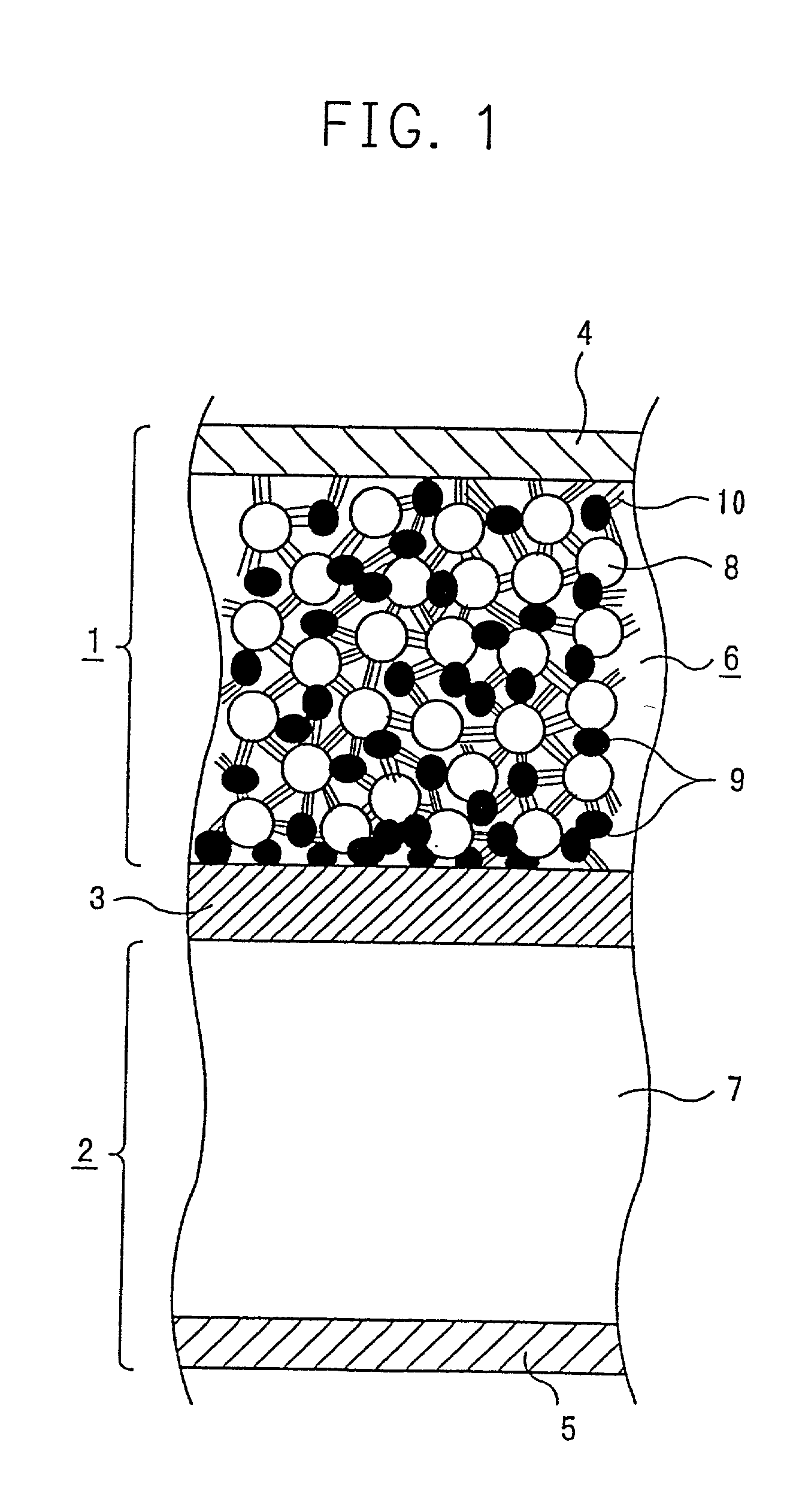
A conventional battery has a problem that a large short-circuit current was generated with temperature rise due to internal short-circuit or the like, and therefore, the temperature of the battery further increases due to exothermic reaction to increase the short-circuit current. The present invention has been carried out in order to solve the above problems. The battery of the present invention is a battery wherein at least one of a positive electrode 1 and a negative electrode 2 comprises an active material layer 6 containing an active material 8 and an electronically conductive material 9 contacted to the active material 8, wherein a solid electrolytic layer 3 is interposed between the above positive electrode 1 and the negative electrode 2, and wherein the above electronically conductive material 9 comprises an electrically conductive filler and a resin so that resistance increases with temperature rise.

Description

[0001] The present invention relates to a battery and a process for preparing the same. More particularly, the present invention relates to a battery in which safety is ensured by controlling temperature rise caused by short-circuit or the like, and a process for preparing the same.[0002] Recently, with development in electronic appliances, high leveling of capacity and output density of a battery used as a power source is being advanced. As a battery, which can satisfy these requirements, attention is paid to a lithium ion secondary battery. The lithium ion secondary battery has an advantageous effect that energy density is high, while a sufficient counterplan for safety is required because a non-aqueous electrolytic solution is used.[0003] As a counterplan for safety it has been conventionally suggested to incorporate a safety valve which releases increased internal pressure, or a PTC device of which resistance increases in accordance with the heat generated from external short ci...

Claims


Application Information

Patent Timeline
Patent Type & Authority Applications(United States)
IPC IPC(8): H01M4/13H01M4/139H01M4/62H01M6/50H01M10/05H01M10/058
CPCH01M4/13H01M4/139H01M4/62H01M4/622H01M4/624H01M10/0525H01M10/0565H01M2200/106Y02E60/122Y10T29/49112Y02E60/10Y02P70/50
Inventor YOSHIOKA, SHOJIKISE, MAKIKOURUSHIBATA, HIROAKISHIOTA, HISASHIARAGANE, JUNAIHARA, SHIGERUTAKEMURA, DAIGONISHIMURA, TAKASHI
Owner MITSUBISHI ELECTRIC CORP
Learn More