Service robot for the automatic suction of dust from floor surfaces

a technology of floor surfaces and cleaning robots, which is applied in the direction of carpet cleaners, distance measurement, instruments, etc., can solve the problems of requiring troublesome change of the suction nozzle, damage to delicate furniture, and time-consuming vacuum cleaning

Inactive Publication Date: 2001-06-21
TECHN FACHHOCHSCHULE BERLIN
View PDF0 Cites 226 Cited by
  • Summary
  • Abstract
  • Description
  • Claims
  • Application Information

AI Technical Summary

Problems solved by technology

Despite of the improvements in certain fields during the years, vacuum cleaning remains a time consuming and exhausting housework with nowaday manual means, because frequent bending, sometimes the moving of objects as well as the strong rubbing of the suction nozzle are required.
Apart from that, because of the inflexible suction nozzles, damage of delicate furniture may occur and when changing from smooth surfaces to carpet-covered surfaces, each time the suction nozzle has to be switched manually to achieve the best cleaning effect.
If narrow places have to be vacuumed, a troublesome change of the suction nozzle is required.
Methods of controlling, which require a manual route planning, are to complicated and very inflexible, because especially in a household, the floor surface which is to be cleaned changes continuously because of the moving of objects.
Apart from that, because of the detection of the border lines, it takes a comparatively long time until the actual suction process starts and the method only works in closed room areas.
Moreover, it is not possible to define a certain starting point for the vacuum cleaner, from where the cleaning process is to be started.
Exclusively stochastic methods of controlling work unsatisfactorily as well, because certain areas are covered very often whereas other areas are covered rarely or not at all, so that an non-uniform cleaning effect is achieved.
In the recursive method of controlling, described in the patent application EP-A-38 26 93, the vacuum cleaner has to cover very far distances because of the continuous moving ahead and moving back, which leads to long vacuuming times and to a non-uniform covering of the area.
The self moving vacuum cleaners controlled by the methods described above are not suitable to replace the manual vacuum cleaners because of the following reasons: Powerful vacuum cleaners possess a bulky form and cannot be used in narrow spaces, also because the damage of delicate furniture cannot be excluded.
Moreover, except from complicated driving methods, several and complicated sensors are used which render the devices susceptible and very expensive.
But this limits the possible size of the batteries and so the reach and the power of the vacuum cleaner, and despite of that, many areas in corners an niches and along the edges of furniture cannot be cleaned, because they are not accessible for the vacuum cleaner.
Vacuum cleaners relying on a wire based power supply, in principal because of the necessary connecting cable are not flexible enough to be able to clean efficiently housing spaces with numerous obstacles.
This feature renders it possible to renounce on an additional outer contact sensor, which would have to surround the device completely and which would be mechanically complicated.

Method used


Image

  • Service robot for the automatic suction of dust from floor surfaces
  • Service robot for the automatic suction of dust from floor surfaces
  • Service robot for the automatic suction of dust from floor surfaces

Examples


Embodiment Construction

[0078] Driving means and concept of movement

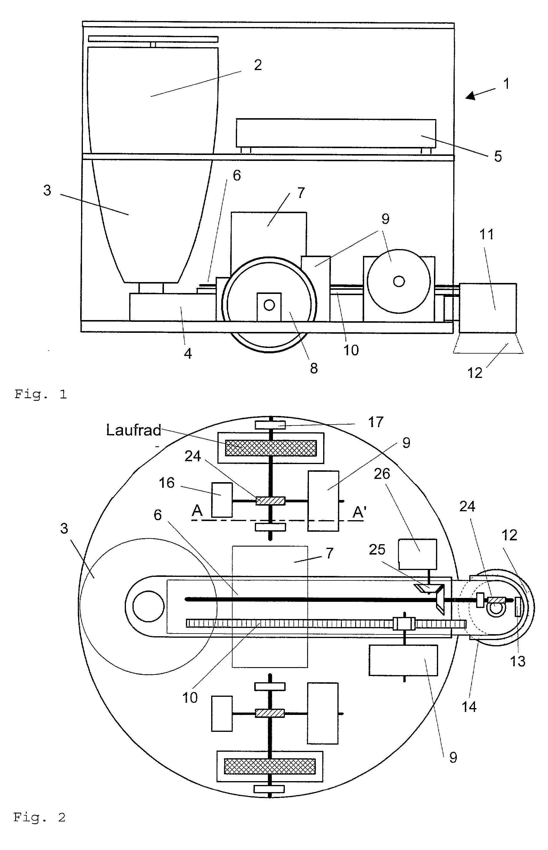
[0079] FIG. 1 shows the elevation of the vacuum cleaner 1 while FIG. 2 depicts the top plan view upon the lower level of the vacuum cleaner 1 with removed dust arrester 3.

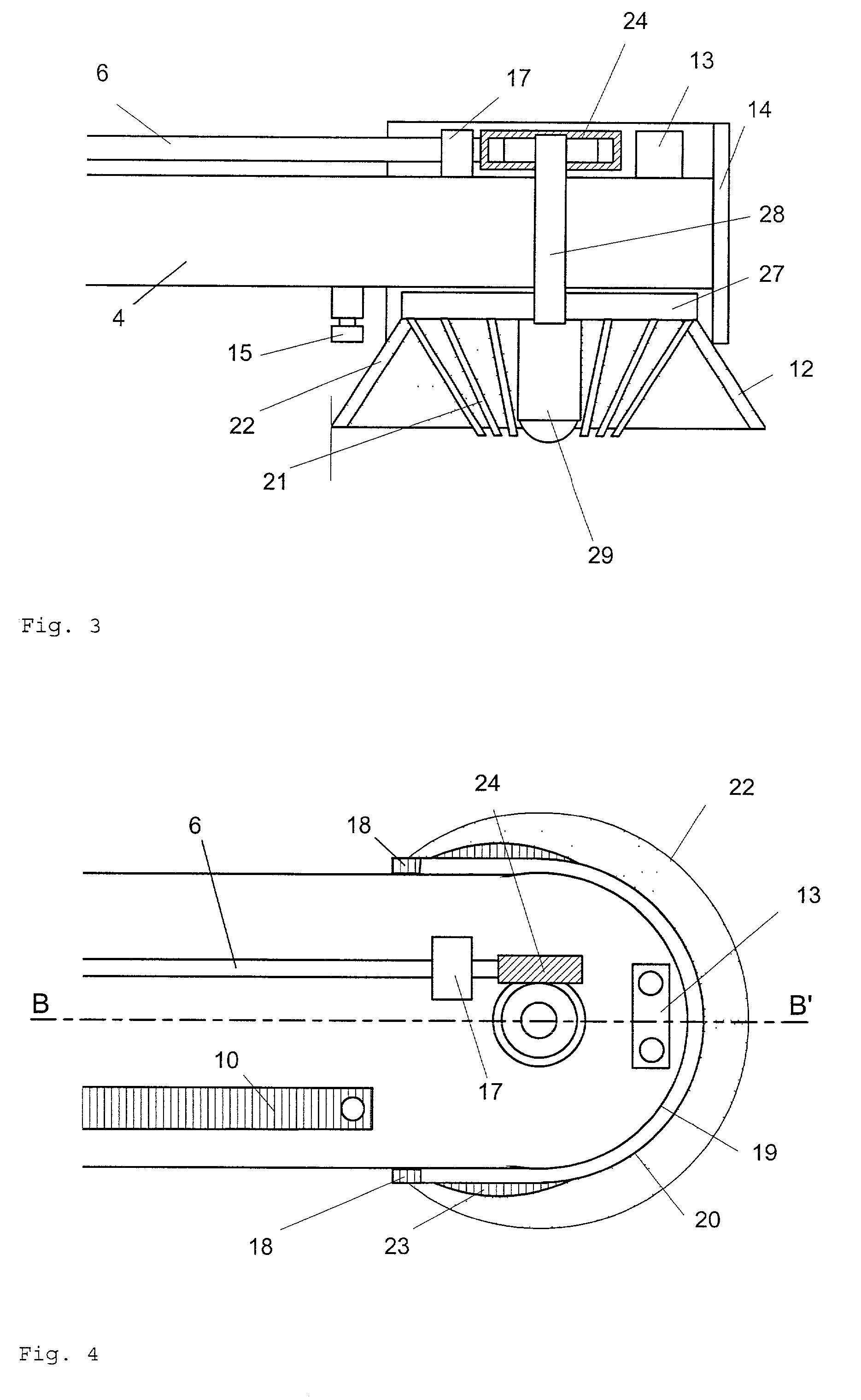
[0080] The drive is realised by two step motors 9, each of which propelling by means of a worm drive 24 with a gear reduction of approx. 1:30 a rubber covered wheel 8. By positioning the wheels 8 on the symmetrical axis of the circular basis, by means of the two motors 9, as well the forward thrust (same direction of turning) as the turning around the centre of the vacuum cleaner 1 (opposite directions of turning) can be realised. As a third support, the cleaning brush 12 is used, which is mounted at the front end of the extensible suction arm 4.

[0081] By positioning the comparatively heavy battery 7, which provides every motor 2, 9, 26 as well as the electronic hardware 5 with energy, on the basis of the cleaner body, it is realised that the vacuum cleaner 1 is provided ...


PUM

PropertyMeasurementUnit
widthaaaaaaaaaa
angleaaaaaaaaaa
turning frequencyaaaaaaaaaa

Abstract

The present invention is used for the complete and fully automatic examination of floor surfaces of all kind as well as for a particularly efficient suction of dust therefrom since the lower areas, the edges and the recessed can be detected. In each case, the robot is controlled so as to explore the adjacent area and to detect the potential obstacles using special sensors before storing them in a data field. The displacement towards a new location is then carried out using the stored data until the whole accessible surface has been covered. One of the main constituent members of the robot consists of an extensible arm that rests on the robot and on which contact and range sensors are arranged. When the robot is used as an automatic vacuum cleaner, an air flow is forced into the robot arm and the -cleaning effect can further be enhanced by providing one or more Circular rotary brushes at the front end of the arm. This invention can essentially be used for domestic or industrial Cleaning purposed with a view to replace traditional vacuum cleaners.

Description

[0001] Nowaday commercial household vacuum cleaners resemble in function and handling basically the models from the beginning of the twentieth century, even if in the fields of improvement oft the suction power, noise emission and air-filters continuous improvements could be reached during the years. The various models available on the market differ apart from their design mainly in the power of their engines, which in some cases can be controlled electronically, the noise damping and the quality of their filters.[0002] The classical floor vacuum cleaner consists of an engine block on wheels, with which by means of a tube various nozzles can be connected. For the suction of floor surfaces, usually a rigid nozzle mounted on a telescope handle, which renders possible to clean an area of about 20 cm width, is used. As an alternative, the engine block can be integrated in the telescope handle. For smooth floor surfaces, most models possess a short brush, which can be pushed out of the n...

Claims


Application Information

Patent Timeline
Patent Type & Authority Applications(United States)
IPC IPC(8): A47L5/30A47L11/12G05D1/02
CPCA47L5/30A47L11/12A47L11/4011A47L11/4038A47L11/4044G05D1/0227G05D1/0255G05D1/0274G05D2201/0215A47L2201/04G05D1/0219
Inventor SOMMER, VOLKER
Owner TECHN FACHHOCHSCHULE BERLIN
Why Eureka
Try Eureka