
Prepreg manufacturing method and manufacturing apparatus

a manufacturing method and technology of a manufacturing apparatus, applied in the direction of coatings, etc., can solve the problems of clogging a pultrusion portion, difficult to run the tape-like reinforcing fiber continuously for a long time, and degrading the grade of the prepreg,

Active Publication Date: 2022-11-15
TORAY IND INC
View PDF31 Cites 0 Cited by
  • Summary
  • Abstract
  • Description
  • Claims
  • Application Information

AI Technical Summary

Benefits of technology

[0020]An object of the present invention relates to a method of producing a prepreg, and is to provide a method and apparatus for producing a prepreg, wherein generation of fuzz is suppressed, continuous production is possible without clogging with fuzz, a reinforcing fiber sheet is uniformly provided and efficiently impregnated with a coating liquid, and the production speed can be made higher.
[0036]The method and apparatus for producing a prepreg according to the present invention make it possible to significantly suppress and prevent clogging with fuzz. Furthermore, the method and apparatus enable the reinforcing fiber sheet to be run continuously at a high speed, and enhance the productivity of the reinforcing fiber sheet having a coating liquid applied thereto. Furthermore, the method and apparatus make it possible to apply a coating liquid to a reinforcing fiber sheet uniformly in the width direction and running direction of the reinforcing fiber sheet and to obtain the reinforcing fiber sheet uniformly impregnated up to the inside thereof with the coating liquid.

Problems solved by technology

This is considered to be intended to disturb part of the arrangement of the reinforcing fiber bundle so that the matrix resin can flow in, but applying this idea to a reinforcing fiber sheet conceivably causes the arrangement of the reinforcing fiber bundle to be disturbed, resulting in not only degrading the grade of the prepreg but also decreasing the mechanical property of FRP.
According to the technology of Patent Literature 2, a tape-like reinforcing fiber passes through a slit-like guider chip with no resin in the fore portion of a die in a crosshead, and accordingly, the fore portion is more likely to be clogged with fuzz and also has no function for removing the fuzz, conceivably making it difficult to run the tape-like reinforcing fiber continuously for a long time.
In addition, the method of Patent Literature 3 makes it more likely that fuzz is retained in a liquid pool during continuous production and that the fuzz clogs a pultrusion portion.
There is a problem in that, in particular, running a strip-like reinforcing fiber bundle continuously at a high speed causes the frequency of clogging with fuzz to be very high, and accordingly, enables production to be carried out only at a very low speed and fails to increase productivity.
In addition, a horizontal type pultrusion method makes it necessary to seal the die hermetically to prevent liquid leakage and makes it insufficient to collect fuzz during continuous production.
Because of this, there is a problem in that not only the movement of the bubbles is inhibited by the coating liquid, but also the impregnation with the coating liquid is inhibited by the bubbles, resulting in low impregnation efficiency.
In this regard, Patent Literature 3 also proposes exhausting bubbles through a vent, but the exhaustion takes place only near the outlet of a die, and the effect of the exhaustion is considered to be limitative.
The nozzle can be optimized with a strand or a roving-form object but does not easily cope with a planar shape such as of a reinforcing fiber sheet.
While passing through this nozzle, a reinforcing fiber sheet generates fuzz, which is conceivably more likely to clog a die when brought into the manifold.

Method used


Image

  • Prepreg manufacturing method and manufacturing apparatus
  • Prepreg manufacturing method and manufacturing apparatus
  • Prepreg manufacturing method and manufacturing apparatus

Examples


example 1

[0179]In the present Example, a prepreg was produced using the external force application mechanisms 50a to 50f totaling six units, three each in the width direction on the wall constituent members 21e and 21f, as shown FIG. 18. Out of these, the external force application mechanisms 50c and 50d were disposed so as to match the center of the wall constituent members 21e and 21f respectively in the width direction and the center of the narrowed section in the width direction, and the spacing (La) between adjacent external force application mechanisms was 100 mm. In addition, external force application mechanisms 50 of an adjusting bolt type shown in FIG. 19 were used as the external force application mechanisms 50a to 50f in the present Example. Furthermore, in the vicinity of the external force application mechanisms 50a to 50f, contact displacement gauges (dial gauges manufactured by Mitutoyo Corporation) were mounted as measurement devices 52a to 52f respectively for measuring the...

example 2

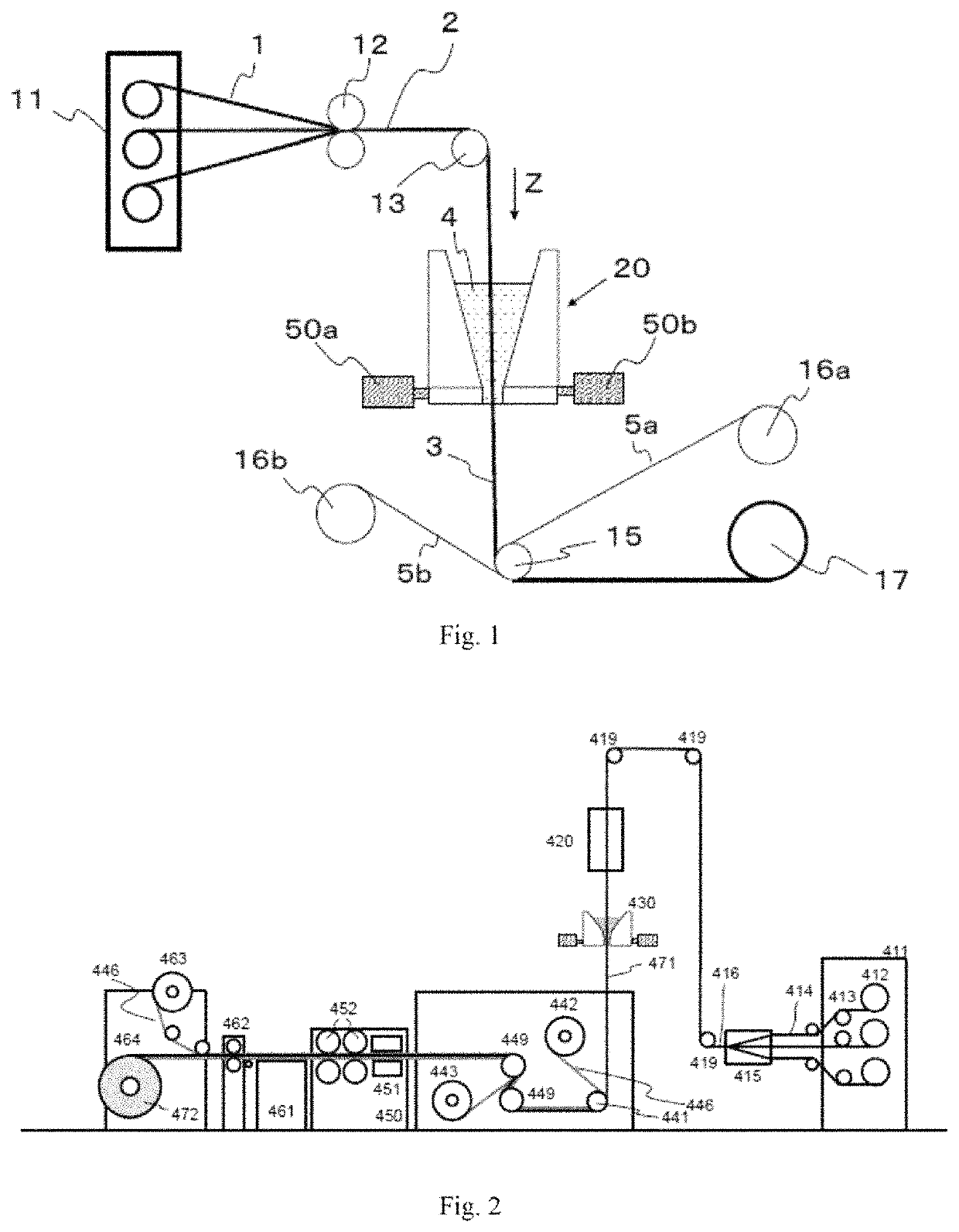
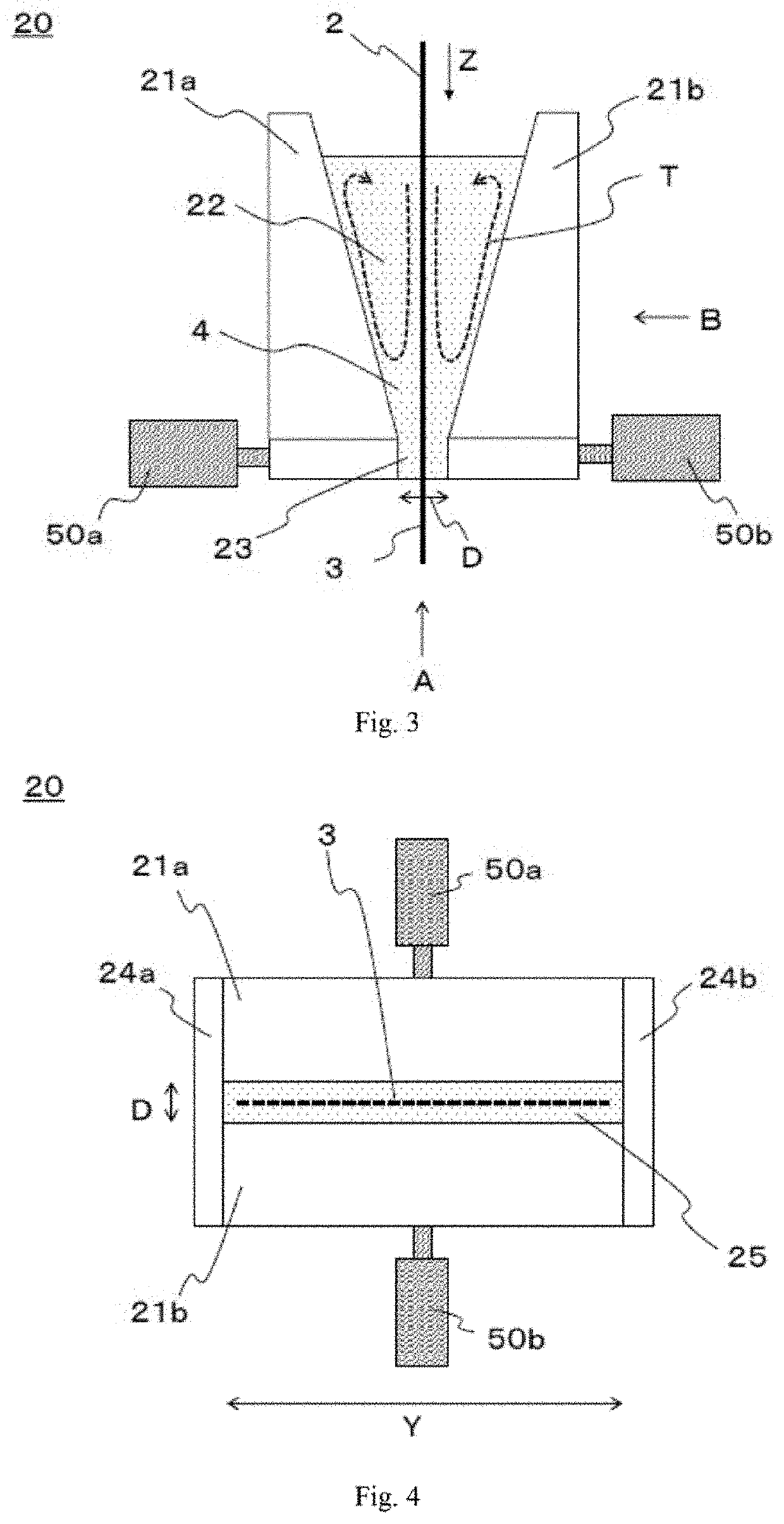
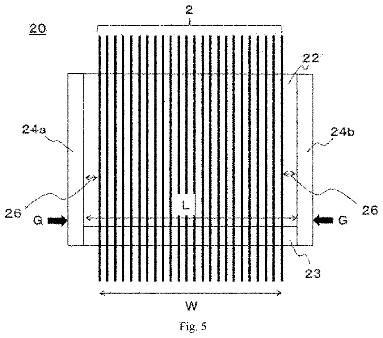
[0184]The coating section 20c of the type depicted in FIG. 9 was used as a coating section, and an apparatus configured as depicted in FIG. 2 and further including a thickness gauge (see FIG. 21; the same in Examples 3 to 13 and Comparative Examples 2 and 3) was used as an apparatus for producing a prepreg. The liquid pool 22 was tapered (the opening angle of the upper taper was 17°, and the opening angle of the lower taper was) 7°. However, the width of the outlet of the narrowed section was 306 mm. In this regard, the gap D in the narrowed section 23 was 0.2 mm, and thus, the aspect ratio of the outlet slit was 1530. In addition, 15 external force application mechanisms of a heat bolt type having a structure depicted in FIG. 20 were mounted at 20 mm intervals on each side of the narrowed section, which was thus sandwiched by the mechanisms (see FIG. 18). A column having a diameter of 10 mm and made of SUS430 (having a thermal conductivity of 15 W / m·° C.) was used as a rod 55 of th...

examples 3 to 9

[0188]A prepreg was produced and evaluated in the same manner as in Example 2 except that the number of external force application mechanisms and the spacing therebetween were changed as in Table 2. At any level, it was possible to take a sample which was rated as usable or better. The results are shown in Table 2.


PUM

PropertyMeasurementUnit
temperatureaaaaaaaaaa
number average particle sizeaaaaaaaaaa

Abstract

The present invention provides an apparatus for producing a prepreg, for applying a coating liquid to a reinforcing fiber sheet, the apparatus including: a coating section including: a liquid pool storing the coating liquid and having a portion whose cross-sectional area decreases continuously and vertically downward, and a narrowed section having a slit-like outlet in communication with the lower end of the liquid pool; a running mechanism for allowing the reinforcing fiber sheet to run vertically downward and be introduced into the coating section; a take-up mechanism for taking up the reinforcing fiber sheet downward from the coating section; wall constituent members opposed to each other in the thickness direction of the reinforcing fiber sheet to form the narrowed section; and an external force application mechanism for applying an external force to the wall constituent members in the thickness direction of the reinforcing fiber sheet.

Description

CROSS REFERENCE TO RELATED APPLICATIONS[0001]This is the U.S. National Phase application of PCT / JP2019 / 032495, filed Aug. 20, 2019, which claims priority to Japanese Patent Application No. 2018-155068, filed Aug. 22, 2018 and Japanese Patent Application No. 2018-155076, filed Aug. 22, 2018, the disclosures of each of these applications being incorporated herein by reference in their entireties for all purposes.FIELD OF THE INVENTION[0002]The present invention relates to a method and apparatus for producing a prepreg, and particularly relates to a method and apparatus for providing and impregnating a reinforcing fiber sheet with a coating liquid uniformly.BACKGROUND OF THE INVENTION[0003]Fiber reinforced composite materials (FRP) in which a matrix resin containing a thermoplastic resin or a thermosetting resin is reinforced with a reinforcing fiber are used in various fields such as aerospace materials, automobile materials, industrial materials, pressure vessels, construction materi...

Claims


Application Information

Patent Timeline
Patent Type & Authority Patents(United States)
IPC IPC(8): B29B15/12C08J5/24C08L63/04
CPCC08J5/243B29B15/122C08L63/04B29B15/125
Inventor NISHINO, SOKONO, YOSHIKAZUOCHI, TAKASHIAOKI, JUNICHIKITAMURA, YOSHIYUKIMINOURA, KIYOSHI
Owner TORAY IND INC
Learn More