Conductive honeycomb structure
a honeycomb and conductive technology, applied in the direction of ceramicware, physical/chemical process catalysts, machines/engines, etc., can solve the problems of unable to efficiently cause the entire catalyst to function efficiently, unable to efficiently cause the entire catalyst to reach the activation temperature, and unable to achieve the effect of achieving the activation temperature efficiently
- Summary
- Abstract
- Description
- Claims
- Application Information
AI Technical Summary
Benefits of technology
Problems solved by technology
Method used
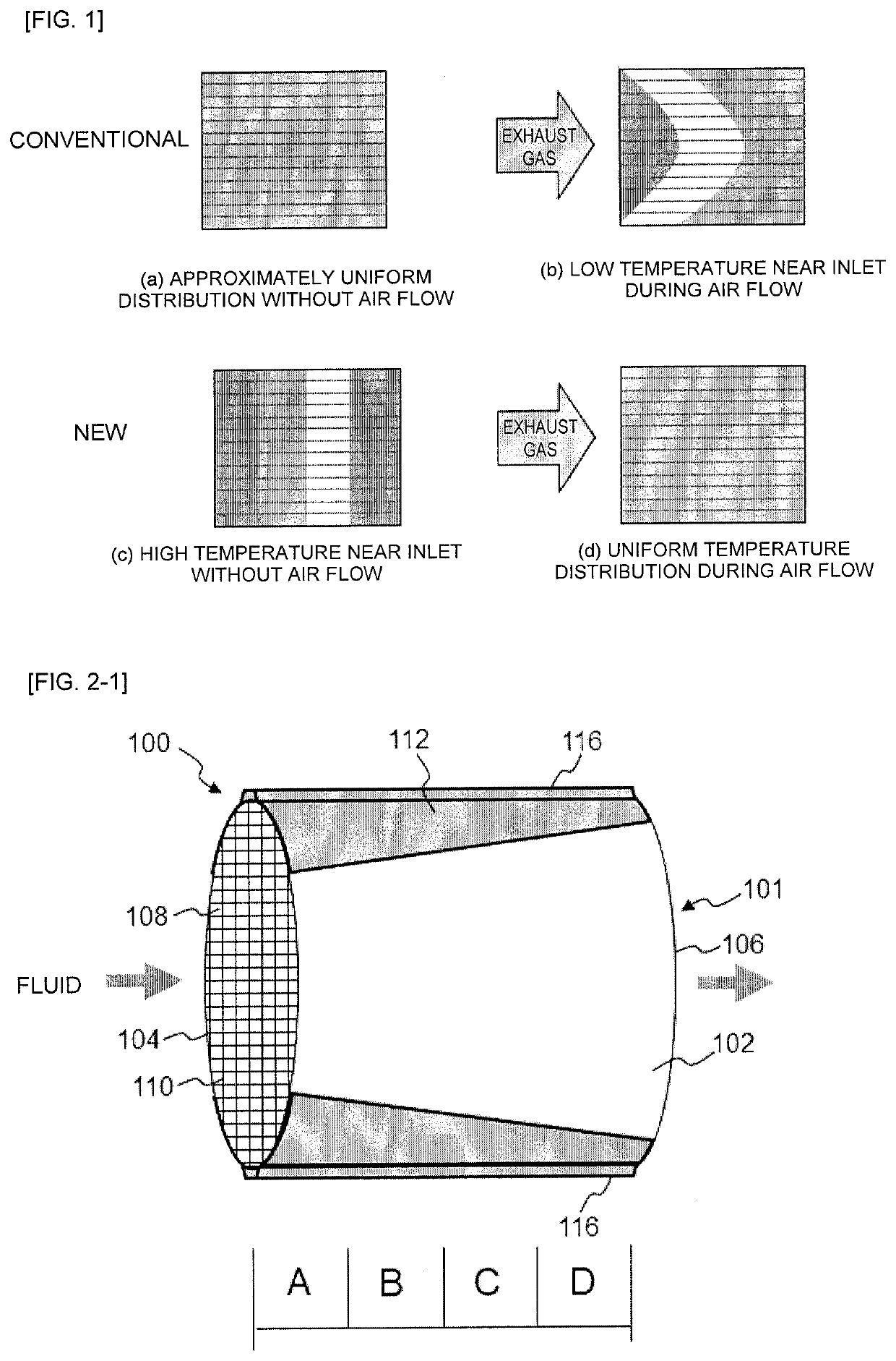
Image

Examples
example 1
(1. Preparation of Cylindrical Green Body)
[0130]A ceramic raw material was prepared by mixing silicon carbide (SiC) powder and metallic silicon (Si) powder at a mass ratio of 80:20. To the ceramic raw material were added hydroxypropylmethyl cellulose as a binder and a water absorbing resin as a pore former, as well as water, to form a molding material. The molding material was then kneaded by a vacuum kneader to prepare a cylindrical green body. The content of the binder was 7 parts by mass when the total amount of silicon carbide (SiC) powder and metallic silicon (Si) powder was 100 parts by mass. The content of the pore former was 3 parts by mass when the total amount of silicon carbide (SiC) powder and metallic silicon (Si) powder was 100 parts by mass. The content of water was 42 parts by mass when the total amount of silicon carbide (SiC) powder and metallic silicon (Si) powder was 100 parts by mass. The mean particle diameter of silicon carbide powder was 20 μm and the mean pa...
PUM
| Property | Measurement | Unit |
|---|---|---|
| voltage | aaaaa | aaaaa |
| voltage | aaaaa | aaaaa |
| voltage | aaaaa | aaaaa |
Abstract
Description
Claims
Application Information
 - R&D
- Intellectual Property
- Life Sciences
- Materials
- Tech Scout
- Unparalleled Data Quality
- Higher Quality Content
- 60% Fewer Hallucinations
Browse by: Latest US Patents, China's latest patents, Technical Efficacy Thesaurus, Application Domain, Technology Topic, Popular Technical Reports.
© 2025 PatSnap. All rights reserved.Legal|Privacy policy|Modern Slavery Act Transparency Statement|Sitemap|About US| Contact US: help@patsnap.com