
Flow triggered gas delivery

a gas delivery and flow technology, applied in the field of flow triggered gas delivery, can solve the problems of no cure for this condition, portable oxygen delivery systems all have drawbacks, portable concentrators are usually bulkier and noisier, and have a relatively short battery li

Active Publication Date: 2022-05-03
METELITS DZHOEL B
View PDF172 Cites 1 Cited by
  • Summary
  • Abstract
  • Description
  • Claims
  • Application Information

AI Technical Summary

Benefits of technology

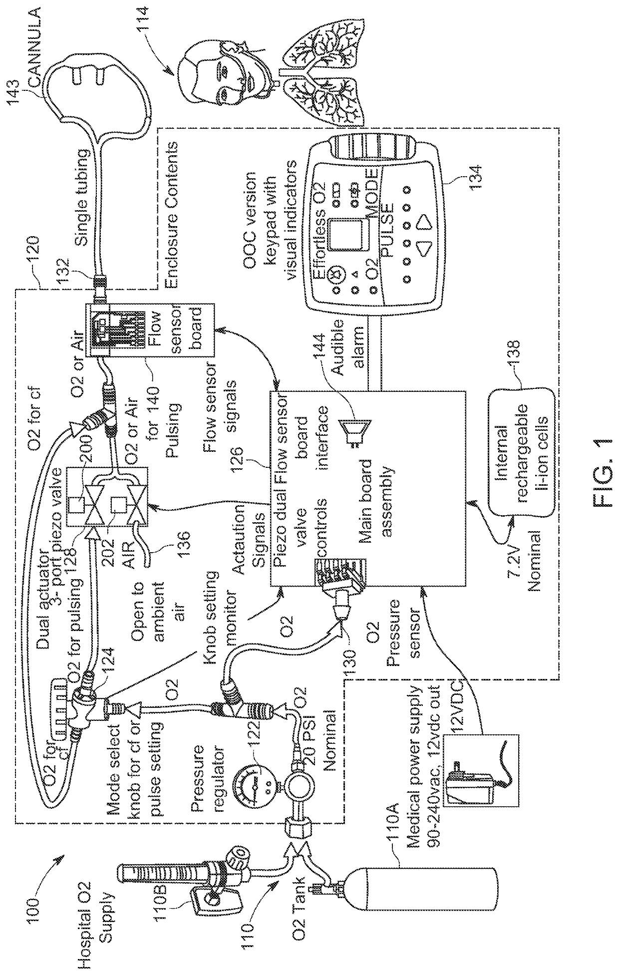
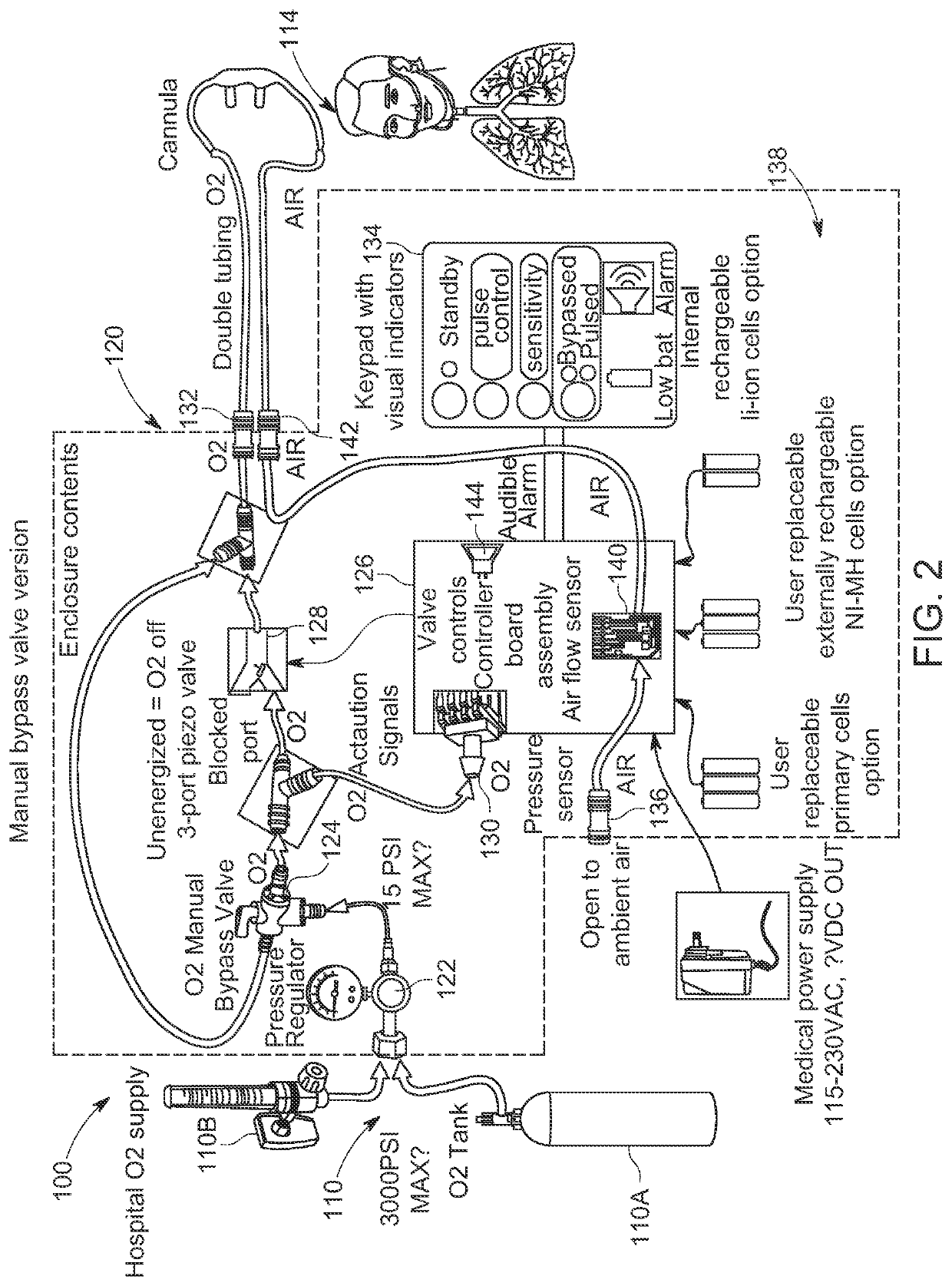
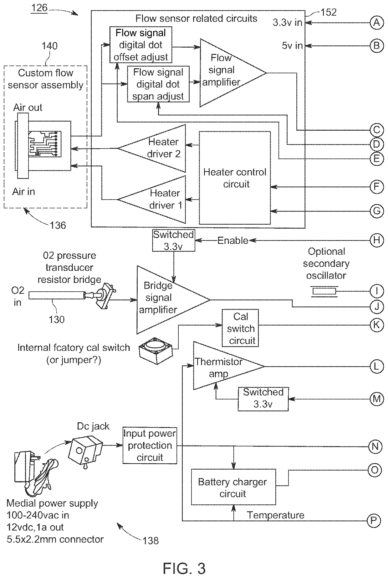
The present invention is an improvement over a previous patent by providing a better trigger mechanism for releasing fluid from a source for delivery to a patient through a nasal or oral cannula. The fluid delivered may be oxygen. The invention utilizes heat and temperature sensors to detect the onset of inspiration by measuring a temperature difference caused by the flow of the fluid. The trigger flow is triggered within less than 20 milliseconds, typically within 10-20 milliseconds, which is much faster than currently available pressure sensors can provide.

Problems solved by technology

Presently there is no cure for this condition.
These portable oxygen delivery systems all have drawbacks.
Portable concentrators are usually bulkier and noisier and have a relatively short battery life.
However, electronic devices cannot be used on all ambulating patients since such high conservation ratios can actually result in poor oxygen saturation for the patient particularly during periods of increased oxygen utilization as in walking vigorously or walking up stairs.
Moreover, currently available conserving devices measure a drop in nasal air pressure, which for many patients is inadequate to trigger the release of oxygen under various circumstances, including: extremely reduced respiratory function; most mouth breathing; talking while walking; while walking briskly or while talking intensely; or while sleeping.
1. Some prior art designs employ a dual lumen cannula in which one of the lumens is dedicated to pressure sensing while the other is dedicated to the supply of oxygen. This design is meant to be more sensitive to the onset of inhalation but suffers from the drawback of only being able to deliver oxygen to one of the nasal passages.
2. Other designs use a single lumen cannula that typically has a pressure sensor connected to a T piece below two nasal prongs. Overall pressure drop associated from inhalation is sensed from both nasal passages and oxygen is then delivered to both nasal passages.
Both designs suffer from a delay in triggering a flow of oxygen due to the hysteresis which is inherent in pressure sensing.
Another drawback of current designs using pressure sensors is that if one of the patient's nasal passages is blocked, it will interfere with the detection and delivery of oxygen.
Yet another flaw with current oxygen generating systems is the fact that a patient's ideal need for oxygen varies with time both in the short term as a result of varying exertion and in the long term as a result of improvement or deterioration in health.
Although there exist theoretical concerns about potential toxicities in patients administered oxygen in high concentrations (above 50 percent) for extended time periods (e.g., absorptive atelectasis, increased oxidative stress, and inflammation), clinical experience has provided little support for these concerns in the setting of LTOT.
Current oxygen treatment plans are prone to error as reported by a study by Fussell et al.
The conclusion of the study was that there was a poor relationship between conventional oxygenation assessment methods and continuous ambulatory oximetry during LTOT screening with COPD patients.
Care Med. 2010 May 15; 181(10): 1061-1071, the current collection of conserving devices all based on pressure sensing were criticized as failing to deliver on their efficacy claims.
The authors claimed that “Although each device activated during nose and mouth breathing, none consistently performed according to engineering expectations.”
When a patient obtains low oxygen saturation results while using conserving devices or fixed oxygen flow rates, the natural response is to simply increase the flow rate, when in actuality, low oxygen saturation results often are caused by a delay in triggering supplemental oxygen flow as early as possible at onset of inhalation.
Increased nasal flow rates become increasingly expensive and are generally not well tolerated.
Some COPD patients who use stationary oxygen concentrators in their homes are financially impaired and are concerned about the power costs of continuously running an oxygen concentrator.
In many cases this has led to a compliance issue where the patient may elect to not switch on the concentrator and follow the therapy as prescribed by the doctor in order to save on their electricity bill.
Moreover, these oxygen concentrators throw a fair amount of heat into the room, which may further add to energy costs, i.e., for cooling the room.
If a patient's resting prescription is 2 liters per minute, the patient may set a flow rate through their cannula to the required flow and the excess oxygen that is being produced is simply pushed into the nostrils which while mouth breathing may be wasted.
Many oxygen therapy patients can spend a significant amount of their time while active, or talking, or napping, or sleeping with blood oxygen saturation levels that are unacceptable.
Current pressure-based oxygen conserving units fail to live up to their claims when a patient is mouth breathing during more vigorous activity, while talking, while eating and / or when sleeping.
When oxygen needs are not being met, the simple solution is to increase the nasal flow rate, which causes increasing problems of uncomfortable nasal passage drying and sometimes nasal mucosal bleeding.
Further, patients often stop their oxygen delivery system altogether when eating.

Method used


Image

  • Flow triggered gas delivery
  • Flow triggered gas delivery
  • Flow triggered gas delivery

Examples


Embodiment Construction

[0035]As used herein “nasal cannula” is intended to include two lumen nasal cannuli as well as nasal masks or pillow masks. And “oral cannula” is intended to include face masks as well as breathing tubes, mouth pieces and the like, as well as diver and hazard helmets and the like.

[0036]Embodiments are described in the following description with reference to the drawing figures in which like numbers represent the same or similar elements. Reference throughout this specification to “one embodiment,”“an embodiment,”“certain embodiments,” or similar language means that a particular feature, structure, or characteristic described in connection with the embodiment is included in at least one embodiment of the present disclosure. Thus, appearances of the phrases “in one embodiment,”“in an embodiment,” and similar language throughout this specification may, but do not necessarily, all refer to the same embodiment.

[0037]The described features, structures, or characteristics of the disclosure...


PUM


Abstract

A fluid delivery system provides fluid, such as supplement oxygen, to a patient in response to inhalation. The fluid delivery system includes a valve assembly that is triggered by sensing onset of inspiration by measuring a change in temperature or fluid flow of air flow in a nasal or oral cannula, mask or helmet.

Description

CROSS REFERENCE TO RELATED APPLICATIONS[0001]This application is a continuation-in-part (CIP) of our copending U.S. patent application Ser. No. 17 / 199,172, filed Mar. 11, 2021 which in turn is a continuation-in-part (CIP) of our copending U.S. patent application Ser. No. 16 / 986,017, filed Aug. 5, 2020, the contents of which are incorporated herein by reference.BACKGROUND OF THE DISCLOSURE[0002]The present disclosure relates to devices and methods for monitoring and delivering oxygen or other gas to a human or other animal, and for effectively conserving the delivery of said gas. The disclosure has particular utility for delivery of supplemental oxygen to a human or animal patient and will be described in connection with such utility, although other utilities are contemplated.[0003]In the U.S. today well over 1.5 million human patients are receiving supplemental oxygen therapy at a cost believed to be excess of 2 billion dollars annually. Moreover, acute cases due to COVID-19 have ex...

Claims


Application Information

Patent Timeline
Patent Type & Authority Patents(United States)
IPC IPC(8): A61M16/20A61M16/00A61M16/06
CPCA61M16/204A61M16/0003A61M16/0666A61M2016/0015A61M2016/0039A61M2202/0208A61M2202/0241A61M2205/3331A61M2205/3368A61M16/024A61M16/06A61M16/0672A61M16/1005A61M16/1075A61M16/125A61M2016/003A61M2202/0275A61M2205/0294A61M2205/18A61M2205/36A61M2205/581A61M2205/583A61M2205/8206A61M2250/00
Inventor METELITS, JOEL B.
Owner METELITS DZHOEL B
Learn More