
Method for manufacturing acrylonitrile based fiber bundle and method for manufacturing carbon fiber bundle

a technology of acrylonitrile and fiber bundle, which is applied in the direction of stretch-spinning methods, dry spinning methods, textiles and papermaking, etc., can solve the problems of insufficient method to meet the object of regulating steam nature in a stable manner, the plasticization effect of the fiber bundle is not efficiently realized, and the fluctuation of temperature and flow rate is difficult to follow. and flow rate, and achieves good flexibility and flexibility. , the effect of high draw ratio

Active Publication Date: 2022-03-29
TORAY IND INC
View PDF11 Cites 0 Cited by
  • Summary
  • Abstract
  • Description
  • Claims
  • Application Information

AI Technical Summary

Benefits of technology

The present invention provides a drawing method for the production of acrylonitrile-based fiber bundles, which are used as precursors for carbon fiber bundles. The method allows for improved processability during pressurized steam drawing at high ratios and speeds, or when producing fine fiber bundles. The method effectively plasticizes the fiber bundles, preventing breakage and fuzz while ensuring stable production of high-quality bundles.

Problems solved by technology

In the method of Patent Document 1, however, it is difficult to follow the fluctuation of the temperature and flow rate of the cooling water or the fluctuation in the nature of the steam supplied, and this method was insufficient to fulfill the object of regulating the steam nature in stable manner.
In addition, the aim of regulating the steam after supplying the steam to the steam drawing apparatus was not always realized by this method even if the steam before being supplied to the steam drawing apparatus were regulated.
The attachment of the drain to the fiber bundle results in the part where the drain has attached and the part where the drain has not attached, and the plasticizing effect of the fiber bundle is not efficiently realized in the part where the drain has not attached, and this often invited breakage of the monofilaments and breakage of acrylonitrile-based fiber bundle.
The method of Patent Document 3 required increase in the production speed if the production capacity was to be improved without large capital investment, and the resulting reduced residence time in the preheating zone and the heating zone was associated with the risk of the breakage of the monofilaments and breakage of the acrylonitrile-based fiber bundle due to the failure of obtaining the amount of heat necessary for the preheating and the drawing.

Method used


Image

  • Method for manufacturing acrylonitrile based fiber bundle and method for manufacturing carbon fiber bundle

Examples


example 1

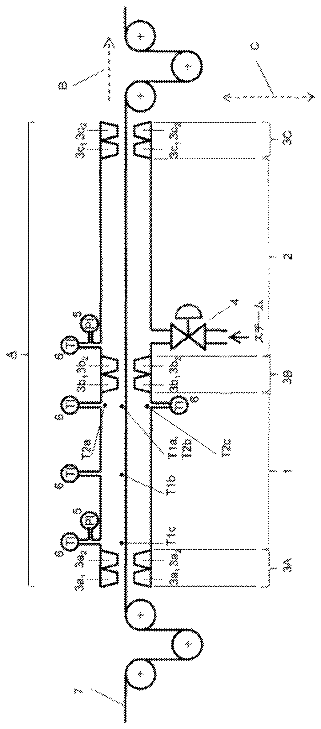
[0054]A solution of acrylonitrile-based copolymer in dimethylsulfoxide containing 99% by mole of acrylonitrile and 1% by mole of itaconic acid was ejected from a 4000 hole nozzle for dry-wet spinning, and 3 bundles were immediately brought together to form a bundle of 12000 filaments. The bundle was drawn at a draw ratio of 2 in a warm water of 40° C., and after washing and further drawing at a draw ratio of 2 in a warm water of 70° C., the bundle was dried to produce a fiber bundle of 12000 filaments having a total dtex of 66000. This fiber bundle was supplied to the steam drawing apparatus shown in FIG. 1, and drawn in the conditions shown in Table 1 to produce an acryl fiber bundle of 12,000 filaments having a unit fineness of 1.1 dtex. The evaluation results of the quality and processability of the resulting acryl fiber bundle and the temperature measurement in the steam drawing apparatus are shown in Table 2.

example 2

[0055]The procedure of Example 1 was repeated except that the pressure in the steam drawing apparatus was changed as shown in Table 1 to obtain the acryl fiber bundle. The evaluation results of the quality and processability of the resulting acryl fiber bundle and the temperature measurement in the steam drawing apparatus are shown in Table 2.

example 3

[0056]The procedure of Example 1 was repeated except that the pressure in the steam drawing apparatus and the temperature of the atmosphere were changed as shown in Table 1 to obtain the acryl fiber bundle. The evaluation results of the quality and processability of the resulting acryl fiber bundle and the temperature measurement in the steam drawing apparatus are shown in Table 2.


PUM

PropertyMeasurementUnit
temperatureaaaaaaaaaa
residence timeaaaaaaaaaa

Abstract

A drawing method is provided which enables a pressurized steam drawing of an acrylonitrile-based fiber bundle used as the precursor fiber of the carbon fiber bundle. In particular, a drawing method is provided which realizes a high processability when this treatment is conducted at a high draw ratio and high speed. This invention is a method for producing an acrylonitrile-based fiber bundle which includes the steps of spinning a spinning solution containing an acrylonitrile-based copolymer, and subjecting the fiber bundle to a pressurized steam drawing in a pressurized steam drawing apparatus (A) having at least two zones which are a preheating zone on the fiber bundle inlet side and a heating zone on the fiber bundle exit side, the two zones being separated by a seal member. The preheating zone is in a pressurized steam atmosphere at 0.05 to 0.35 MPa, the heating zone is in a pressurized steam atmosphere at 0.45 to 0.70 MPa, temperature difference ΔT1 in the preheating zone of the steam drawing apparatus in the fiber bundle-moving direction defined in the specification is up to 5° C., and temperature difference ΔT2 in the preheating zone of the steam drawing apparatus in the cross-sectional direction of the steam drawing apparatus defined in the specification is up to 5° C.

Description

CROSS REFERENCE TO RELATED APPLICATIONS[0001]This is the U.S. National Phase application of PCT / JP2018 / 009194, filed Mar. 9, 2018, which claims priority to Japanese Patent Application No. 2017-049437, filed Mar. 15, 2017, the disclosures of these applications being incorporated herein by reference in their entireties for all purposes.FIELD OF THE INVENTION[0002]The present invention relates to a method for stably producing a high quality acrylonitrile-based fiber bundle which is adapted for use in the production method of a carbon fiber bundle.BACKGROUND OF THE INVENTION[0003]In the production of an acrylonitrile-based fiber bundle which is used as a precursor fiber for the carbon fiber bundle, use of the drawing by pressurized steam has been known since high temperature can be obtained by using hot water at atmospheric pressure, and presence of moisture has the effect of plasticization of the acrylonitrile-based fiber bundle which in turn enables drawing at a high drawing ratio. Ho...

Claims


Application Information

Patent Timeline
Patent Type & Authority Patents(United States)
IPC IPC(8): D01D5/04D01D5/06D01D10/02D02J1/22D02J13/00D01F6/18D01D5/16D01F6/38D01F9/22
CPCD01F6/18D01D5/16D01F6/38D01F9/225D02J1/222D02J1/225D10B2321/10D01D13/02D01F9/22
Inventor IKUTA, HIROYOSHIOHASHI, TAKEYATAMURA, TOMOKI
Owner TORAY IND INC
Learn More