Digital load pull tuner

a digital load and tuner technology, applied in the direction of impedence networks, waveguide devices, electrical devices, etc., can solve the problems of reducing the tuning range of the tuner, introducing insertion loss, and dut cannot be “matched”, so as to minimize spurious reflection and insertion loss, improve compactness, and improve the effect of compactness

Active Publication Date: 2022-01-04
TSIRONIS CHRISTOS
View PDF8 Cites 1 Cited by
  • Summary
  • Abstract
  • Description
  • Claims
  • Application Information

AI Technical Summary

Benefits of technology

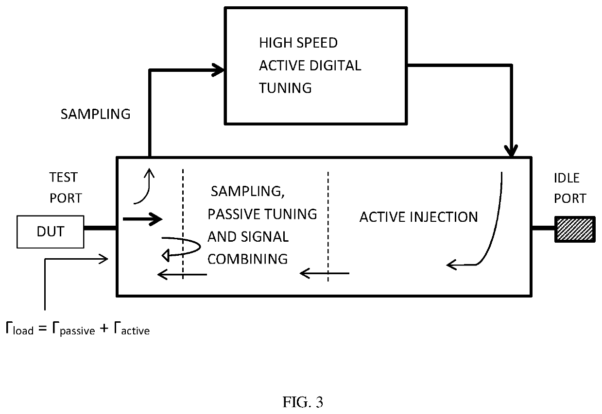
[0013]The digital load pull tuner includes a closed-loop active tuner module and a remotely controlled passive pre-matching tuner module (FIG. 2, 3). A central slabline can be used to integrate the couplers of the closed-loop active tuner and the remotely controlled tuning probes of the passive tuner (FIG. 5). The two modules can also operate separately using two cascaded slablines, but complete integration inside the same slabline improves compactness and minimizes spurious reflections and insertion loss. The signal from the DUT is coupled into the closed loop of the active tuner, where it is digitally amplitude and phase modulated, amplified and coupled back into the slabline towards the DUT. The non-coupled portion of the signal from the DUT is reflected back at the passive tuner and the signal is super-imposed on the active loop signal, thus creating a modulated return signal into the DUT creating a combination of physical and virtual reflection factor (FIG. 5): T=(<α2.phys>+<a2.virt>) / <b2>, wherein <b2> is the DUT outgoing signal, <a2.phys> is the reflected signal at the remotely controlled passive tuner and <a2.virt> is the feedback injected active signal. Only <a2.virt> is digitally modulated and allows high speed tuning. <a2.phys> allows directing (pre-matching) the load pull vector close to the optimum DUT matching load (FIG. 5, 8).

Problems solved by technology

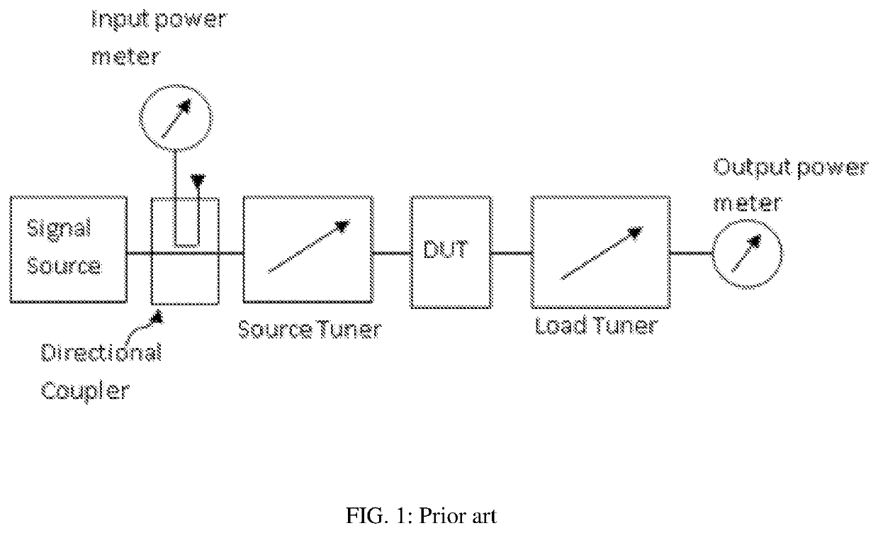
Embedding the DUT in fixtures and connecting with the tuners introduces insertion loss.
This reduces the tuning range of the tuners, to the point that the DUT cannot be “matched”, i.e. it cannot be presented physically the optimum load to obtain the target performance.
To increase power capability of active tuners requires very high power, expensive, amplifiers.
4) has been abandoned by the market because of their limited linearity and tuning range, compared to electro-mechanical slide screw tuners (see ref.

Method used


Image

  • Digital load pull tuner
  • Digital load pull tuner
  • Digital load pull tuner

Examples


Embodiment Construction

[0028]In a first embodiment of the invention (FIGS. 2 and 5) the signal exiting from the DUT output port enters the tuner into the test port (50); then it is sampled by the first adjustable coupler (51), FIG. 12, of which the coupling factor and phase are controlled by approaching its coupling loop (51) to the center conductor of the slabline (53) via the vertical axis (56) and motor (52) and its phase by changing the physical distance of the coupling loop (51) from the test port (50). The coupled signal portion propagates from port (57) through an optional filter to port 1 of circulator (58). From port 1 the signal is transferred with negligible insertion loss to port 2 where it is reflected back at the test port of the digital solid-state tuner (59). The multitude of reflection factors generated by the digital tuner is shown in FIG. 7A; this means the amplitude and phase of the reflected signal wave is digitally modulated by ΓET=|ΓET|*exp(jΦET), as shown in FIG. 7A. The reflected ...


PUM


Abstract

A digital high-speed load pull tuner comprises a slide screw automatic tuner in a traditional reflection configuration and an active forward injection loop using a digital tuner in a transmission configuration. The forward active injection loop comprises two compact signal couplers of which at least one is adjustable, a digital tuner, circulator, feedback power amplifier; the passive tuner comprises one or more remotely controlled mobile carriages sliding along the slabline and carrying metallic tuning probes, used to create passive reflection factors. The incoming signal is sampled, modulated in amplitude and phase by the digital tuner and fed back into the slabline synchronizing with the passive reflected signal, to create a partially virtual load presented to the DUT.

Description

PRIORITY CLAIM[0001]Not applicableCROSS-REFERENCE TO RELATED ARTICLES[0002]1. Load Pull, [online] Wikipedia, [Retrieved on 2016 Nov. 18]. Retrieved from Internet <URL: https: / / en.wikipedia.org / wiki / Load_pull>[0003]2. “Computer Controlled Microwave Tuner, CCMT”, Product Note 41, Focus Microwaves Inc. 1998, pages 2-4.[0004]3. Verspecht et al. U.S. Pat. No. 7,282,926, “Method and an apparatus for characterizing a high-frequency device-under-test in a large signal impedance tuning environment”.[0005]4. Woodin Jr. et al., U.S. Pat. No. 5,276,411, “High power solid-state programmable load”.[0006]5. Simpson, G, US application Publication US 2013 / 0321092 A1, “Hybrid Active Tuning Systems and Methods”, FIGS. 3, 6 and 9-22.[0007]6. Tsironis, C. U.S. Pat. No. 9,921,253, “Method for reducing power requirements in active load pull system”.BACKGROUND OF THE INVENTION AND PRIOR ART[0008]Introductory remark: Throughout this disclosure items on figures start with the number of the figure, for ...

Claims


Application Information

Patent Timeline
Patent Type & Authority Patents(United States)
IPC IPC(8): H01P5/04H03H7/38
CPCH01P5/04H03H7/38
Inventor TSIRONIS, CHRISTOS
Owner TSIRONIS CHRISTOS
Why Eureka
Try Eureka