Exhaust purification unit

a technology of exhaust gas purification and purification unit, which is applied in the direction of machines/engines, mechanical equipment, separation processes, etc., can solve the problems of reducing reducing the exhaust gas purification capacity of the scr catalyst, and deteriorating the diffusivity of ammonia in the exhaust gas supplied to the scr catalyst, so as to improve the hydrolysis efficiency of urea water and improve the exhaust gas purification capacity of the catalyst. ,

Active Publication Date: 2021-10-19
ISUZU MOTORS LTD
View PDF44 Cites 0 Cited by
  • Summary
  • Abstract
  • Description
  • Claims
  • Application Information

AI Technical Summary

Benefits of technology

[0012]According to the exhaust purification unit of the disclosure, it is possible to increase a hydrolysis efficiency of the urea water and to improve diffusivity of ammonia in the exhaust gas, thereby improving an exhaust gas purification capacity of the catalyst.

Problems solved by technology

As a result, a hydrolysis efficiency of the urea water is lowered and diffusivity of ammonia in the exhaust gas supplied to the SCR catalyst is deteriorated, so that an exhaust gas purification capacity of the SCR catalyst is lowered.

Method used


Image

  • Exhaust purification unit
  • Exhaust purification unit
  • Exhaust purification unit

Examples


Embodiment Construction

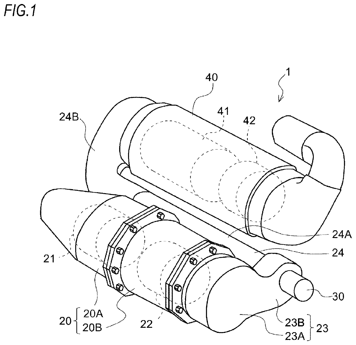
[0023]Hereinafter, illustrative embodiments of the disclosure will be described with reference to the drawings. FIG. 1 is a perspective view depicting an exhaust purification unit 1 in accordance with an illustrative embodiment. As shown in FIG. 1, the exhaust purification unit 1 includes a front stage casing 20, a mixer chamber 23, a urea water injection valve 30, a connecting pipe 24 and a rear stage casing 40 in corresponding order from an exhaust upstream-side.

[0024]The front stage casing 20 and the rear stage casing 40 have a cylindrical shape, and are arranged in parallel so that both axis lines thereof are parallel with each other and are connected by the connecting pipe 24 arranged therebetween. The connecting pipe 24 has a cylindrical first pipe 24A and is arranged so that an axis line of the pipe 24A is parallel with the axis lines of the front stage casing 20 and the rear stage casing 40.

[0025]The front stage casing 20 has a first casing 20A and a second casing 20B coaxia...


PUM


Abstract

An exhaust purification unit includes: a connecting pipe transmitting exhaust gas to a selective reduction catalyst (SCR); a urea water injection valve arranged to face an exhaust upstream end of the connecting pipe and injecting urea water into the connecting pipe; a mixer chamber forming a flow path along which exhaust gas flows from an exhaust downstream end of a front stage casing and turns back to the exhaust upstream end of the connecting pipe; and a flow adjustment member provided in the mixer chamber, being a member having a truncated-cone shape which extends from a vicinity of the injection opening of the urea water injection valve towards the connecting pipe with a diameter thereof gradually increasing, in which a plurality of small holes is formed, and in which a claw that guides the exhaust gas towards the exhaust downstream-side is provided for each of the plurality of small holes.

Description

CROSS-REFERENCE TO RELATED APPLICATIONS[0001]This application is a U.S. National Stage entry of PCT Application No. PCT / JP2016 / 060217, filed on Mar. 29, 2016, which claims priority to Japanese Patent Application Nos. 2015-068050, filed Mar. 30, 2015 and 2015-085716, filed Apr. 20, 2015, the contents of which are incorporated herein by reference.TECHNICAL FIELD[0002]The present invention relates to an exhaust purification unit having an SCR catalyst.BACKGROUND ART[0003]As an exhaust purification unit reducing and purifying a nitrogen compound (NOx) in exhaust emitted from an internal combustion engine, there has been known an exhaust purification unit which includes a front stage part having a filter trapping particulate matters (hereinafter, referred to as ‘PM’) in an oxidation catalyst and the exhaust and a rear stage part having a selective reduction catalyst (hereinafter, referred to as ‘SCR catalyst’) purifying the nitrogen compound (hereinafter, referred to as ‘NOx’) in the exh...

Claims


Application Information

Patent Timeline
Patent Type & Authority Patents(United States)
IPC IPC(8): F01N3/20B01D53/94F01N3/24F01N3/08F01N3/28
CPCF01N3/208B01D53/94F01N3/08F01N3/2066F01N3/24F01N3/2892F01N2240/20F01N2240/40F01N2610/02Y02T10/12
Inventor OOHARA, ISAOOSADA, KATSUSHI
Owner ISUZU MOTORS LTD
Why Eureka
Try Eureka