
Display panel with distributed driver network

Active Publication Date: 2021-03-16
SOLOMON SYSTECH SHENZHEN LTD
View PDF24 Cites 5 Cited by
  • Summary
  • Abstract
  • Description
  • Claims
  • Application Information

AI Technical Summary

Benefits of technology

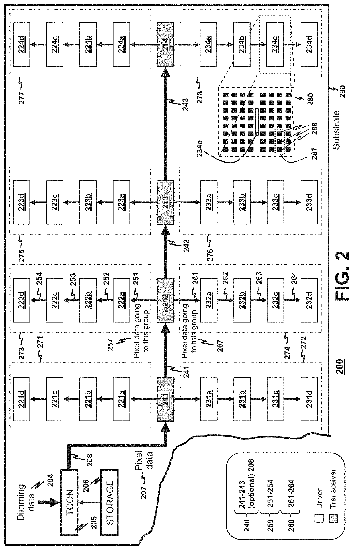
The patent text describes a display panel that uses a first and second linear daisy chain to transmit pixel data to drivers, resulting in more reliable transmission of data compared to broadcasting it unselectively. The panel has a compact design with a reduced data-line footprint. Additionally, the panel has a pixel-driving network and a pixel-data distribution network for delivering pixel data to the drivers. The panel also includes a backlight and a LC layer for controlling the intensity of the backlight. These features improve the dynamic range of the light intensity and enhance the colors of the display.

Problems solved by technology

In a display panel having an array of LEDs for backlight generation or for direct image generation, it is increasingly challenging to drive the LED array as the panel size increases.
Driving the LED array is especially challenging when the display panel has a very large display area, e.g., when the display panel is used as a road-side advertisement board.
If the LED array is realized as a passive matrix, there is a limitation on the number of rows that a single LED driver can serve.
It affects the smoothness in displaying moving pictures and also limits the maximum brightness each LED can provide.
Usually, a single driver is limited to drive 200 rows of LEDs in the passive matrix.
However, as the panel size increases, a greater proportion of driving power from the LED driver is used in driving parasitic resistance and capacitance inherent in source electrodes that connect to LEDs rather than powering the LEDs.
Furthermore, the maximum frame-refresh rate is inversely proportional to the number of rows, making it difficult to maintain the smoothness in displaying moving pictures if the LED driver is used to drive a large number of rows.
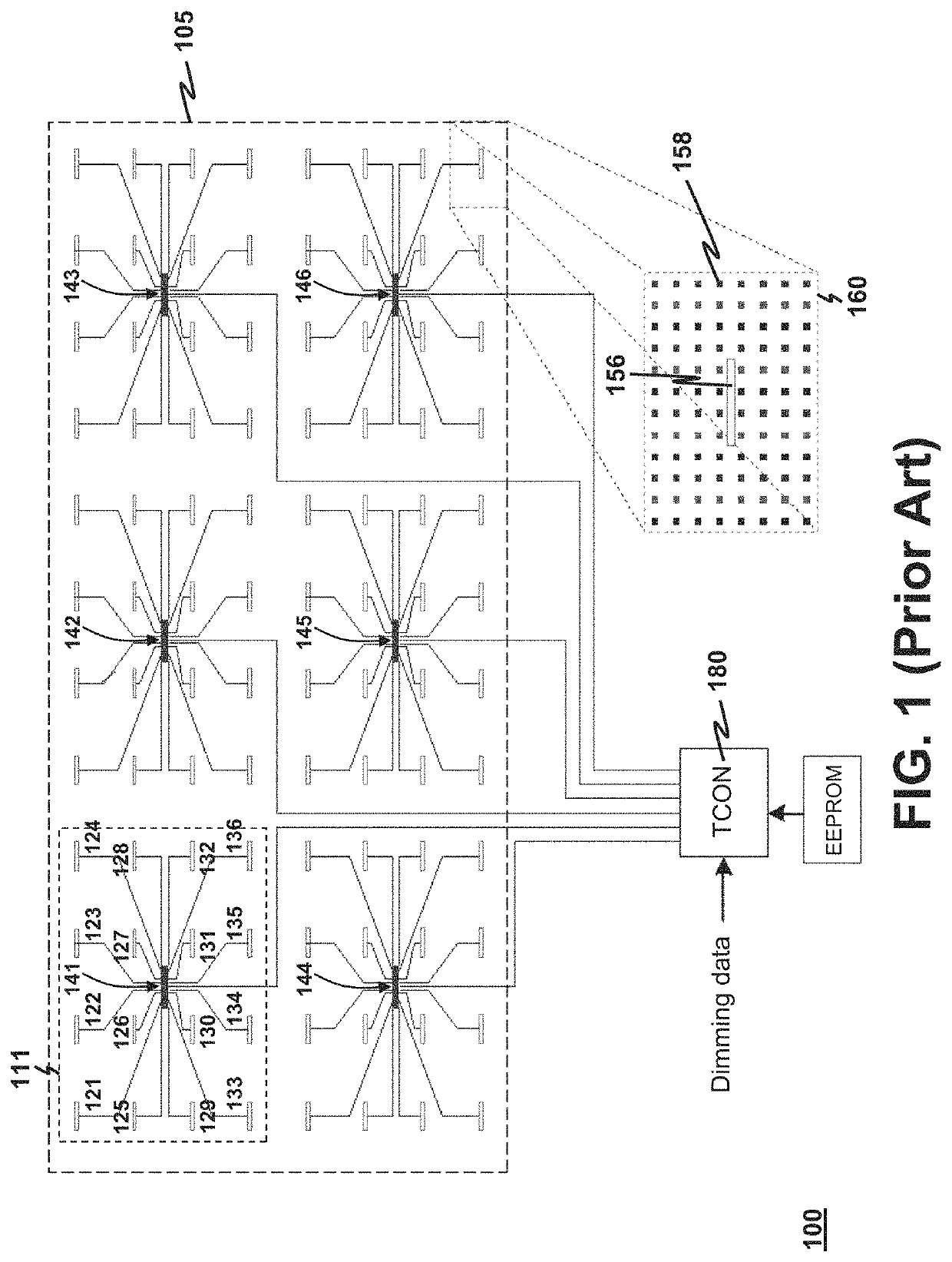
A major disadvantage of using the star topology in networking the TCON, transceivers and drivers is that a lot of data lines are required to be installed in forming a star-topology network.
It leads to a high data-line footprint on a substrate on which the pixels, transceivers and drivers are mounted.
Both consequences lead to a high cost in manufacturing the display panel.

Method used


Image

  • Display panel with distributed driver network
  • Display panel with distributed driver network
  • Display panel with distributed driver network

Examples


Embodiment Construction

[0056]As used herein, “a data-line footprint” means a percentage of a substrate surface being laid with data lines. Therefore, a high data-line footprint implies that the remaining area of the substrate surface usable for mounting with different ICs for performing desired functions is reduced.

[0057]As used herein, “a data line running generally along a direction” means a data line following a path such that at least 60% of the length of the path substantially follows the aforesaid direction. Hence, such data line has at least 60% of its length to be a straight line and to run along a dedicated direction. Despite such data line has occasional bends caused by, e.g., IC pins blocking a straight path intended to be followed by the data line, a major proportion of the data line being straight (greater than 60%) and running along one direction promotes reliable transmission of data.

[0058]Disclosed herein is a display panel having a reduced data-line footprint when compared to a convention...


PUM


Abstract

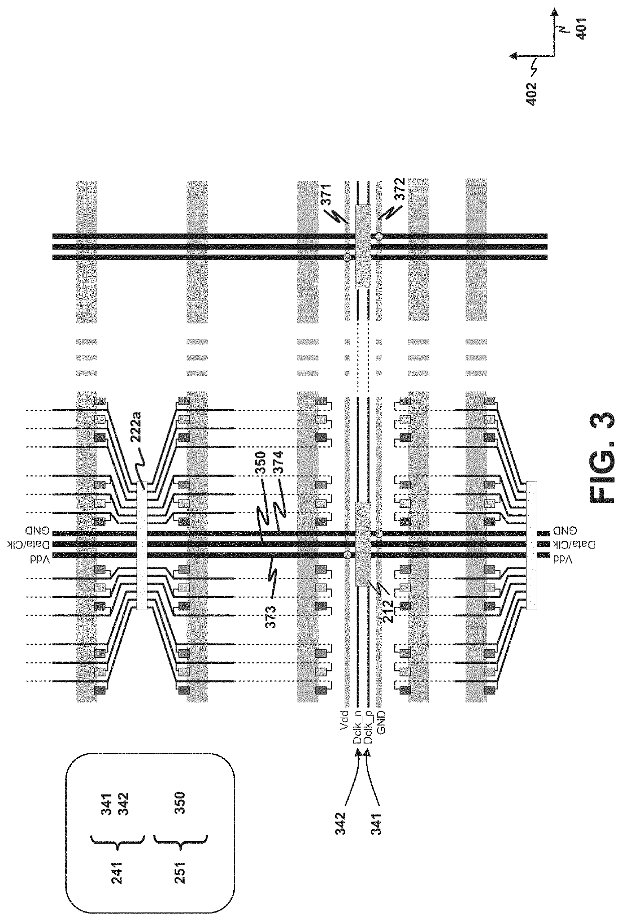
In a display panel, drivers for driving LEDs of pixels are distributed over a substrate, and transceivers relay pixel data from a timing controller to the drivers. The drivers are divided into groups. Respective drivers in a group receive corresponding pixel data addressed thereto solely from one corresponding transceiver. The corresponding transceiver and the respective drivers are daisy-chained to form one first linear daisy chain, where each pair of immediately-adjacent first drivers are connected. Plural first linear daisy chains are formed for all groups. The transceivers are daisy-chained to form a second linear daisy chain by connecting each pair of immediately-adjacent transceivers. The first and second linear daisy chains form a fishbone topology network to enable transmission of pixel data from the timing controller to the drivers while reducing a data-line footprint on the substrate that mounts the pixels, driver and transceivers in comparison to a conventional star-topology network.

Description

LIST OF ABBREVIATIONS[0001]2D Two-dimensional[0002]EEPROM Electrically erasable programmable read-only memory[0003]EMI Electromagnetic interference[0004]GND Ground[0005]IC Integrated circuit[0006]ID Identification[0007]LC Liquid crystal[0008]LED Light emitting diode[0009]OLED Organic LED[0010]PCB Printed circuit board[0011]PLL Phase locked loop[0012]RLL Run length limited[0013]TCON Timing controllerFIELD OF THE INVENTION[0014]The present invention generally relates to a display panel. In particular, the present invention relates to a display panel having a distributed driver network mounted on a substrate for driving a plurality of light-generating pixels where the distributed driver network exhibits a reduced data-line footprint on the substrate.BACKGROUND[0015]In a display panel having an array of LEDs for backlight generation or for direct image generation, it is increasingly challenging to drive the LED array as the panel size increases. Driving the LED array is especially chall...

Claims


Application Information

Patent Timeline
IPC IPC(8): G09G3/36G09G3/00
CPCG09G3/3648G09G3/006G09G3/3688G09G3/3696G09G2330/026G09G2330/027G09G3/3406G09G3/36G09G2300/026G06F3/1446G09G5/006G06F3/1431G09G5/12G09G2370/14G09G5/10
Inventor CHAN, WING CHI STEPHENLEE, CHI WAIKE, PIE CHIHLO, JOHNKID
Owner SOLOMON SYSTECH SHENZHEN LTD
Learn More