
Glass for laser processing and method for producing perforated glass using same

a laser processing and perforation technology, applied in glass making apparatus, glass making tools, welding/soldering/cutting articles, etc., can solve the problems of high cost, high production cost of monocrystalline silicon, and high cost of silicon wafers

Active Publication Date: 2020-07-21
NIPPON SHEET GLASS CO LTD
View PDF35 Cites 5 Cited by
  • Summary
  • Abstract
  • Description
  • Claims
  • Application Information

AI Technical Summary

Benefits of technology

The glass enables efficient, cost-effective production of perforated glasses with uniform holes, suitable for display devices and electronic components, using a nanosecond Nd:YVO laser, reducing processing costs and preventing alkali contamination.

Problems solved by technology

However, production of monocrystalline silicon, which is a main material of silicon wafers, requires very high cost, so that silicon wafers are also very expensive.
Furthermore, laser processing employing ablation, which is a practically used technique for forming holes in silicon wafers, necessarily involves applying a plurality of laser pulses to form one hole and has difficulty in achieving high-speed processing.
That is, such laser processing employing ablation requires a long tact time and hence a high processing cost.
However, the composition of the glass disclosed in the examples includes such a large amount of alkali metal in the form of oxide that the glass has a higher coefficient of thermal expansion than silicon wafers and is unsuitable for use in MEMS or electronic devices.
The glass is thus prone to devitrification, which is disadvantageous for continuous production.
Furthermore, an alkali component contained in the composition can contaminate device production lines.

Method used


Image

  • Glass for laser processing and method for producing perforated glass using same
  • Glass for laser processing and method for producing perforated glass using same

Examples


examples

[0168]Hereinafter, the present invention will be described in more detail by way of examples. The present invention is by no means limited by these examples, and many modifications are possible by any ordinarily skilled person in the art within the technical concept of the present invention.

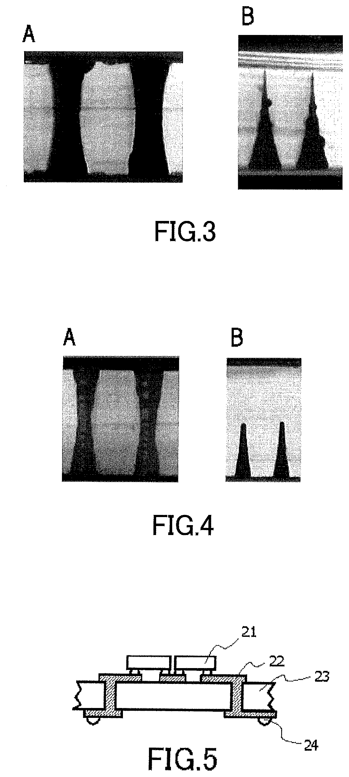
[0169]Examples in which glass substrates having different compositions were subjected to hole forming will be described below, along with the description of hole quality evaluations. The hole quality evaluations were made according to the criteria described below. All of the evaluations were made by observation or examination after laser irradiation and completion of perforation by etching. “Good” means a practically acceptable level, while “poor” means an unacceptable level.

[0170](1) Circularity or Contour

[0171]Openings of approximately circular holes formed in each glass substrate (or in its surface) were evaluated. The glass substrate was rated as “good” if the ratio of the largest diameter to...


PUM

PropertyMeasurementUnit
wavelengthaaaaaaaaaa
temperatureaaaaaaaaaa
heightaaaaaaaaaa

Abstract

The present invention provides a glass composition that allows holes with a circular contour and a smooth inner wall to be formed by a collective micro-hole-forming process using a combination of modified portion formation by ultraviolet laser irradiation and etching, the glass composition being adapted for practical continuous production. The present invention relates to a glass for laser processing, the glass including a metal oxide serving as a coloring component, the glass having a glass composition including, in mol %: 45.0%≤SiO2≤68.0%; 2.0%≤B2O3≤20.0%; 3.0%≤Al2O3≤20.0%; 0.1%≤TiO2≤5.0%; and 0%≤ZnO≤9.0%, wherein a relationship of 0≤Li2O+Na2O+K2O<2.0% is satisfied.

Description

TECHNICAL FIELD[0001]The present invention relates to a glass for laser processing and a method for producing a perforated glass using the glass for laser processing.BACKGROUND ART[0002]Components having an array of a large number of minute through holes are used as microscopic elements for MEMS or electronic devices. As such components there are generally used silicon wafers whose expansion and contraction due to temperature change is small (CTE=around 35×10−7 / ° C.) and which are thus resistant to breakage. Silicon wafers, which have a low coefficient of thermal expansion (CTE), are also characterized by undergoing little change in properties in response to temperature change. However, production of monocrystalline silicon, which is a main material of silicon wafers, requires very high cost, so that silicon wafers are also very expensive. Furthermore, laser processing employing ablation, which is a practically used technique for forming holes in silicon wafers, necessarily involves...

Claims


Application Information

Patent Timeline
Patent Type & Authority Patents(United States)
IPC IPC(8): C03C3/093B23K26/06C03B33/02C03C3/091C03C15/00B23K26/00B23K26/70C03C23/00B23K26/352C03C4/00C03C3/095B23K26/53B23K103/00
CPCC03C3/091C03B33/0222B23K26/70C03C4/0071C03C23/0025C03C3/095C03C3/093C03C15/00B23K26/53B23K26/0006B23K26/0648B23K26/352B23K2103/54B81C1/00595C03C3/087C03C4/00Y02P40/57
Inventor INOUE, TERUHIDEKURACHI, JUNJI
Owner NIPPON SHEET GLASS CO LTD
Learn More