Slide screw tuners with offset tuning probes and method

a technology of offset tuning and slide screw, which is applied in the direction of channel estimation, transmission, coupling devices, etc., can solve the problems of reducing the tuning range of insertion loss and the inability to reach the internal impedance of high-power devices in the area of item b>31/b> using traditional passive tuners

Active Publication Date: 2020-06-16
TSIRONIS CHRISTOS
View PDF3 Cites 6 Cited by
  • Summary
  • Abstract
  • Description
  • Claims
  • Application Information

AI Technical Summary

Benefits of technology

[0014]In the case (a): Typical internal impedance of microwave power transistors (FIG. 3) is in the area of the spot 30. Whereas the tuning range 32 of the tuner itself can reach this point, after inserting the RF cable (FIG. 11) the tuning range is reduced 33, in which case the impedance at point 30 cannot be reached. This leads to the requirement of minimizing insertion loss (see FIG. 11). Realistically, high power devices having internal impedance in the area of item 31 cannot be reached using traditional passive tuners. Four parts contribute to the insertion loss: (1) the insertion loss of the wafer probe itself; (2) the insertion loss of the RF cable, (3) the insertion loss of the test port adapter, and (4) the insertion loss of the slabline section 20 between test port and tuning probe. This invention discloses a tuner, which eliminates items (2) (the RF cable) and (3) (the test port adapter) and minimizes item (4) (the slabline section between test port and tuning probe). To improve the manufacturability of extremely straight center conductors, case (b), we chose to make the slabline as short as possible. To do so, the invention introduces extended tuning probe brackets (FIGS. 5 and 8). The tuning probes are not mounted coaxially below the vertical axis of the carriages but offset, such that at initialization the tuning probes are placed as close to the test port as physically possible. By minimizing insertion loss, areas in the vicinity of item 31 are reachable. This is most important for millimeter-wave frequencies, where cable and adapter loss are high and item 31 is closer to the center of the Smith chart and can be easily tuned to.

Problems solved by technology

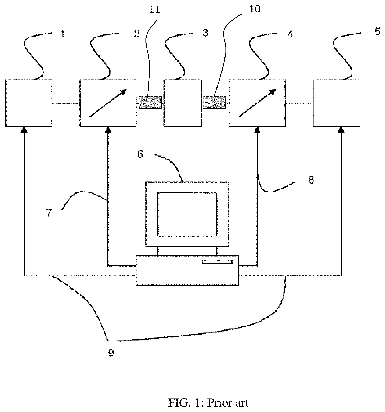
The major limitations with passive slide screw tuners are: (a) the insertion loss shown in FIG. 1 as items 10 and 11 and FIG. 11 between the tuner test port and the DUT; the insertion loss reduces the tuning range (FIG. 3); (b) the mechanical width (in horizontal direction) of the mobile carriage(s), especially in multi-carriage tuners, dictates a minimum length of the tuner and the slabline, especially at high frequencies, where the electrical length is short and the center conductor very thin.
Realistically, high power devices having internal impedance in the area of item 31 cannot be reached using traditional passive tuners.

Method used


Image

  • Slide screw tuners with offset tuning probes and method
  • Slide screw tuners with offset tuning probes and method
  • Slide screw tuners with offset tuning probes and method

Examples


Embodiment Construction

[0028]The new tuner structure is shown in FIGS. 5, 6, 8, 9 and 10. FIG. 5 depicts the single probe tuner. The housing 502 is longer, because it holds the horizontally 501 movable mobile carriage 58, the horizontal motor 503 and the horizontal gear 504 and does not include the shorter slabline 52. The slabline 52 has now as short a length 54, as required by the horizontal travel of the tuning probe 53 to cover 360 degrees of reflection factor at Fmin (lambda / 2) and no more. This is possible by using the extension bracket 505 mounted on the vertical axis 51, controlled by motor 57. This way the tuning probe 53 can be placed immediately next to the test port 56. The total length of the slabline 54 can be optimized as a function of Fmin without regard of the auxiliary tuner mechanics. The actual distance 50 between test port 56 and vertical axis 51 is now shortened by the length 55 of the bracket 505. In addition the housing 502 and slabline 52 can be shaped in bullet form (FIG. 10) to ...


PUM


Abstract

A passive slide screw load pull tuner structure can be used on-wafer, in millimeter-wave frequencies from 25 to 110 GHz and above. It uses special tuning probe brackets and a short slabline mounted below the tuner housing, which holds the control gear. The tuner is mounted under an angle matching the angle of the wafer-probe, is connected directly of the wafer-probe and ensures optimum tuning range.

Description

PRIORITY CLAIM[0001]This application is a division of U.S. Non-Provisional patent application Ser. No. 16 / 038,431, filed Jul. 18, 2018, and titled “Slide Screw Tuners With Offset Tuning Probes and Method”, which is incorporated herein by reference in its entirety.CROSS-REFERENCE TO RELATED ARTICLES[0002]1. “Load Pull” [online] Wikipedia, [Retrieved on 2017 Aug. 24]. Retrieved from Internet <URL: https: / / en.wikipedia.org / wiki / Load_pull>.[0003]2. “Computer Controlled Microwave Tuner, CCMT”, Product Note 41, Focus Microwaves Inc. 1998, pages 2-4.[0004]3. “Standing wave ratio” [online], Wikipedia, [Retrieved on 2017 Feb. 3]. Retrieved from Internet <URL: https: / / en.wikipedia.org / wiki / Standing_wave_ratio>.[0005]4. Tsironis, U.S. Pat. No. 6,674,293, “Adaptable pre-matched tuner system and method”[0006]5. “MPT, a universal Multi-Purpose Tuner”, Product Note 79, Focus Microwaves Inc., October 2004.[0007]6. “On Wafer Load Pull Tuner Setups: A Design Help”, Application Note 48, Fo...

Claims


Application Information

Patent Timeline
Patent Type & Authority Patents(United States)
IPC IPC(8): H03H7/40G01R31/28H04L25/02H01P5/18H01P5/04G01R31/26H03H7/38
CPCH01P5/04H01P5/18H03H7/38G01R31/2614H04L25/0278G01R31/2822H03J1/06H03J1/08H03J7/305H04L25/0204H04L25/0228H04L25/03343H04L25/03891
Inventor TSIRONIS, CHRISTOS
Owner TSIRONIS CHRISTOS
Why Eureka
Try Eureka