
Method for the optoinjection of exogenous material into a biological cell

a biological cell and exogenous material technology, applied in the field of optoinjection of exogenous material into biological cells, can solve the problems of inability to accurately position the focal spot of a laser beam on the cell membrane, affecting the synthesis of enzymology, and requiring laborious laser beam alignment,

Active Publication Date: 2020-05-19
FOND INST ITAL DI TECH
View PDF1 Cites 0 Cited by
  • Summary
  • Abstract
  • Description
  • Claims
  • Application Information

AI Technical Summary

Benefits of technology

[0018]The Applicant also noted that, although using a Bessel beam can simplify the focusing of the laser beam on the cell membrane, the membrane perforation using Bessel beams may require a relatively high optical power to obtain a sufficient energy fluence in the central region of the beam. Such a power could produce undesired thermal effects in some types of cells.
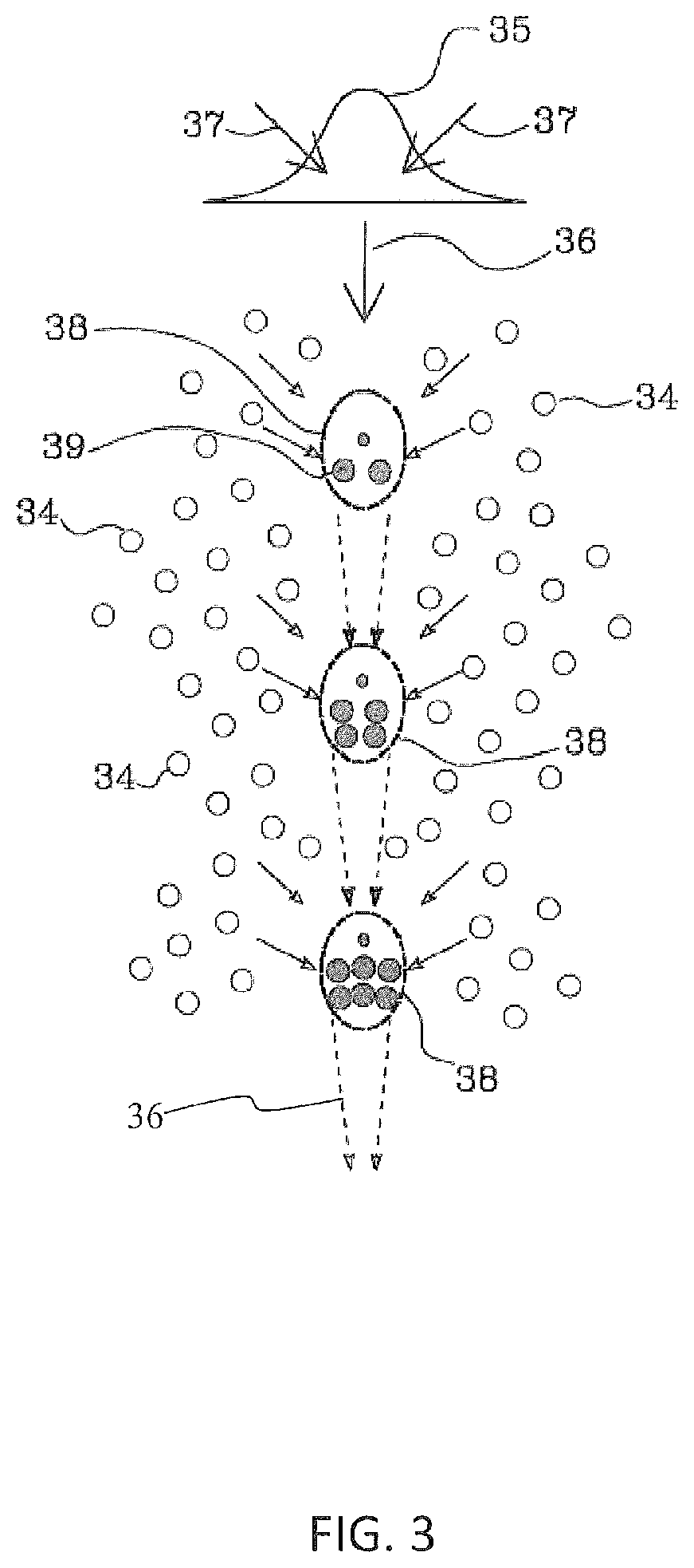
[0019]The exogenous materials to be transfected or in general, to be introduced within a living biological cell is typically contained in a liquid solution in contact with the outer surface of the cell, in the description below also referred to as extracellular solution. In many cases of interest, the recipient biological cell is immersed in the extracellular solution. The Applicant has understood that a continuous displacement of the focal spot of the laser beam through a solution containing exogenous material towards the recipient cell allows an efficient injection of exogenous material flow into the cell. In particular, the Applicant has understood that since a focused laser beam having relatively high optical power generates a very localized optical tweezers effect that attracts the molecules of the fluid, a continuous laser displacement generates a stream of extracellular solution optically directed towards the cell, thereby increasing the optical injection efficiency.
[0020]The Applicant has also understood that an electronic control of the axial displacement of the focused optical beam towards the cell has several advantages, among which allowing the beam to be kept on only during the descent of the focal spot towards the cell and switching the beam off when it is in an axial position within the cell, thereby reducing the photodamage induced by the optical beam into the cell.
[0023]In some preferred embodiments, the optoinjection process may be repeated at least a second time and in general a desired number of times by bringing the switched-off beam back to an axial position outside the cell and above it. Once the beam has been switched on again, the process involves continuously axially moving the focal spot in the direction of the cell until the beam penetrates into the cell itself. In this way, it is possible to increase the amount of injected exogenous material and automate the optoinjection process, thereby improving the efficiency thereof.
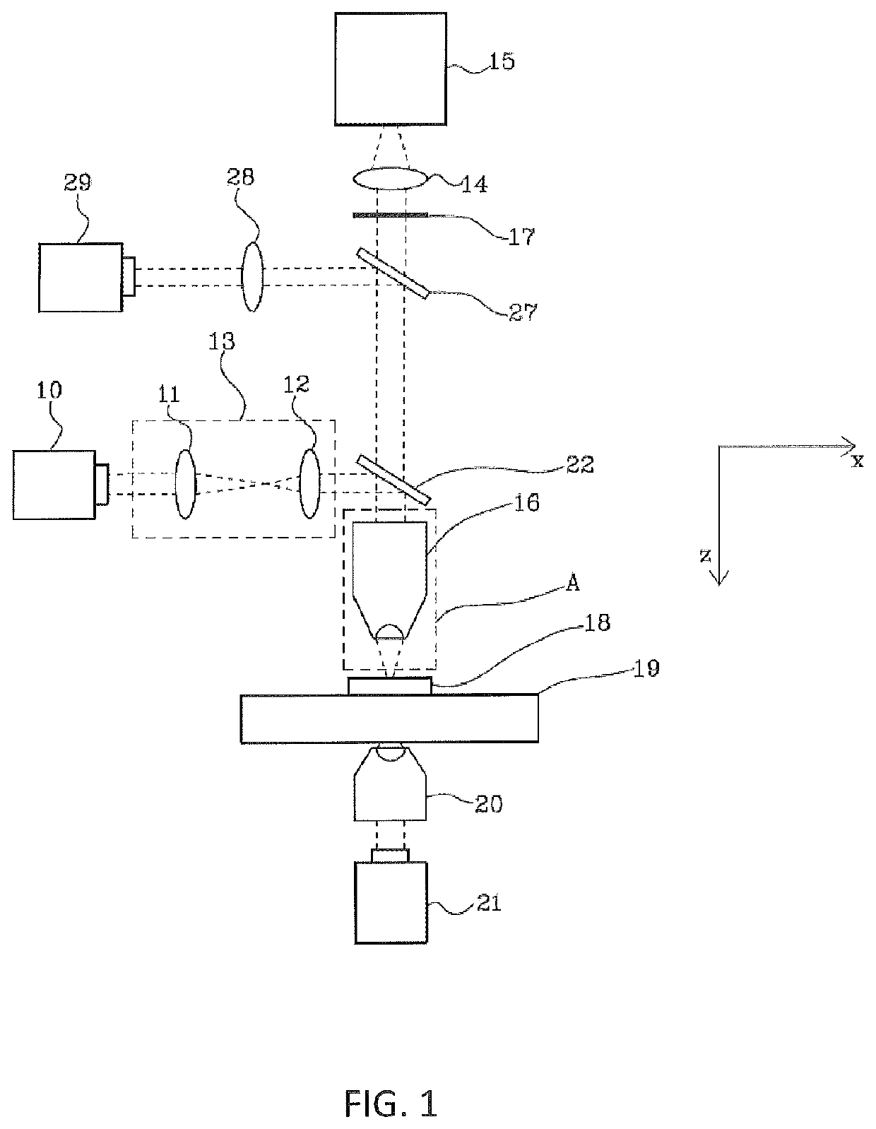
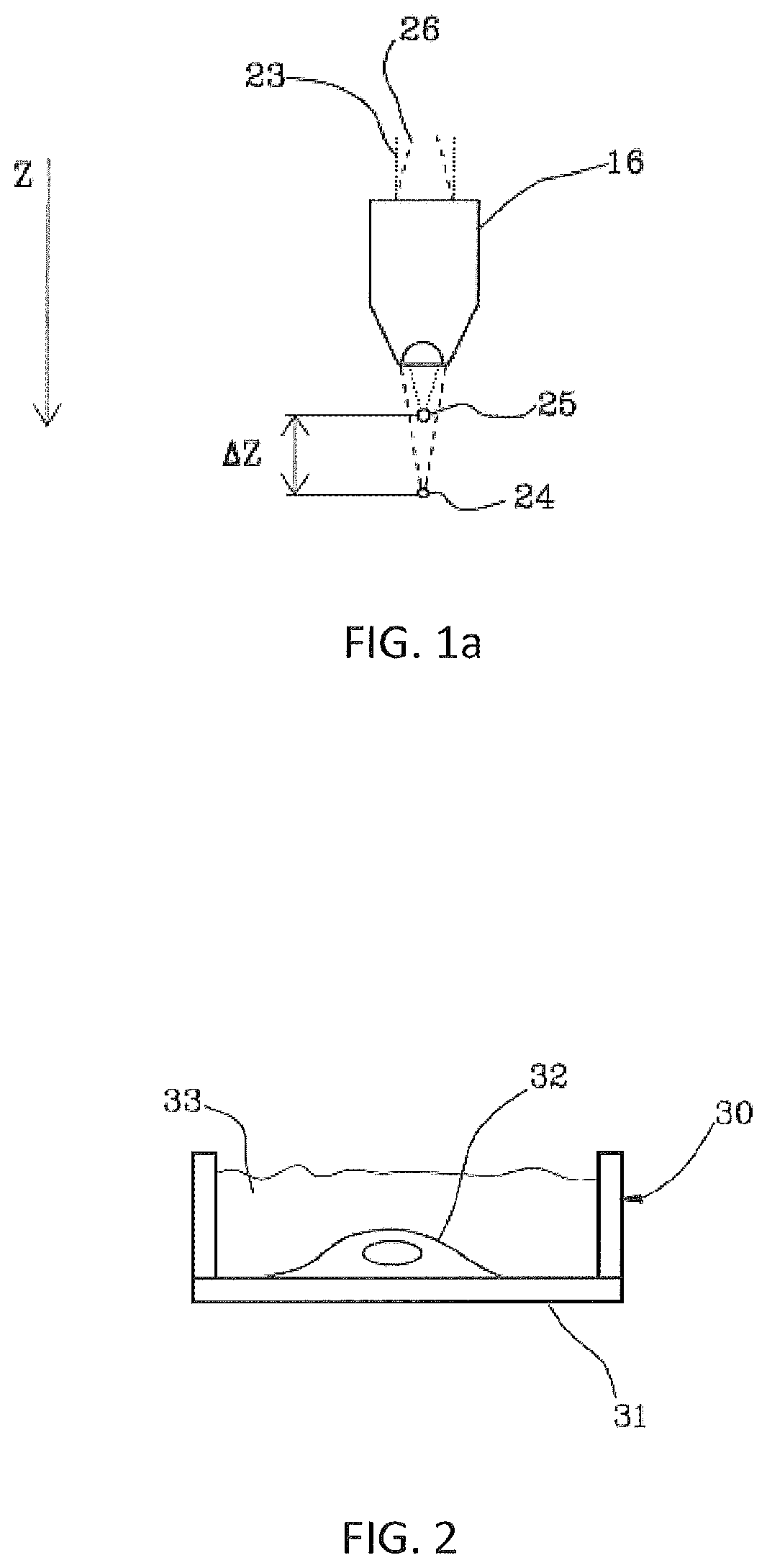
[0029]moving the focal spot towards the cell along the axial direction by continuously varying the control electric signal from the first amplitude value to a second amplitude value, the second amplitude value defining a second focal length corresponding to a second axial position zf of the focal spot, wherein the second amplitude value of the control signal is selected such that the second axial position is positioned inside the cell, at a second axial distance from the planar surface of the substrate, less than the first axial distance, such that the focal spot traverses the membrane of the cell during the descent of the focal spot towards the cell producing a pore in the membrane, which allows the fluid solution containing exogenous material to enter the cell.
[0030]The method according to the present disclosure allows the optoinjection of a single cell with sub-cellular accuracy.

Problems solved by technology

The Applicant noted that an accurate positioning of the focal spot of a laser beam on the cell membrane is often complex and in most cases requires a laborious alignment of the laser beam.
An incorrect positioning of the focal spot on the membrane can lead to having a relatively large percentage of failure of injection of extracellular material or irreversible damage to the transfected cell.
Such a power could produce undesired thermal effects in some types of cells.

Method used


Image

  • Method for the optoinjection of exogenous material into a biological cell
  • Method for the optoinjection of exogenous material into a biological cell
  • Method for the optoinjection of exogenous material into a biological cell

Examples


example

[0138]FIGS. 6a to 6f show a series of fluorescence microscope images captured before, during and after the optoinjection of a neuronal cell, respectively. Neuronal cells were incubated with a saline solution for cells containing fluorescent dyes FM1-43 in a glass Petri dish. The Petri dish had a base that was the substrate on which the cells, and in particular the recipient cell, were resting. Molecules FM1-43 are known to increase the quantum yield when they interact with the cell's membrane phospholipid layers, and it is therefore possible to detect the flow of the solution inside the cell when the membrane is pierced by the laser beam, since the molecules enter and interact with the membranes of the intracellular organelles. FIG. 6a is an image showing the target (recipient) cell highlighted by a contour indicated with an arrow, before the optoinjection. The white spots in FIG. 6a represent three dead cells that emit a fluorescent light saturated signal due to uncontrolled absorp...


PUM

PropertyMeasurementUnit
speedaaaaaaaaaa
sizeaaaaaaaaaa
sizeaaaaaaaaaa

Abstract

A method for the optoinjection of exogenous material in a recipient biological cell is disclosed and comprises: placing a biological cell on a planar surface of a substrate, transmitting a sub-ns pulsed laser beam through a variable convergence / divergence collimator; focusing the laser beam in a focal spot positioned along an axial direction substantially perpendicular to the substrate; moving the focal spot towards the cell along the axial direction by continuously varying the electric control signal from a first amplitude value a second amplitude value the second amplitude value of the control signal is selected such that the second axial position is positioned inside the cell.

Description

CROSS REFERENCE TO RELATED APPLICATIONS[0001]This application is a 35 USC § 371 national stage application of PCT / IB2016 / 057829, which was filed Dec. 20, 2016 and claimed priority to IT 102015000088892, filed Dec. 30, 2015, both of which are incorporated herein by reference as if fully set forth.FIELD OF THE INVENTION[0002]The present invention relates to a method for the optoinjection of exogenous material into a biological cell.BACKGROUND OF THE INVENTION[0003]The introduction of exogenous genetic material (transgene) or foreign molecules in living cells has been found, during the last decades, to be a powerful tool in modern molecular biology. In the case of incorporation of exogenous DNA molecules in eukaryotic cells, usually mammals, it is called transfection, which may be transient or stable. More generally, the interest is for the incorporation of different materials foreign to the cell, such as imaging agents, peptides, antibodies, enzymes or pharmacologically active molecul...

Claims


Application Information

Patent Timeline
Patent Type & Authority Patents(United States)
IPC IPC(8): C12N15/87C12N13/00C12M1/42B23K26/06B23K26/04B23K26/0622B23K26/384C12N5/00
CPCC12N13/00B23K26/0648C12M35/02B23K26/0624B23K26/048C12N15/87B23K26/384C12N5/0006
Inventor DIFATO, FRANCESCOSOLOPERTO, ALESSANDROPALAZZOLO, GEMMA
Owner FOND INST ITAL DI TECH
Learn More