
Method for image data acquisition with a magnetic resonance device

a magnetic resonance device and image data technology, applied in the direction of magnetic measurements, measurement devices, instruments, etc., can solve the problems of difficult to repeat the acquisition, the number of artifacts known that can occur, and the difficulty of obtaining images

Active Publication Date: 2011-12-27
SIEMENS HEALTHCARE GMBH
View PDF15 Cites 1 Cited by
  • Summary
  • Abstract
  • Description
  • Claims
  • Application Information

AI Technical Summary

Benefits of technology

[0009]An object of the present invention is to provide a method with which the field of view can be established (in particular in the phase coding direction) so that the region of interest is free of aliasing and the field of view is optimally small.
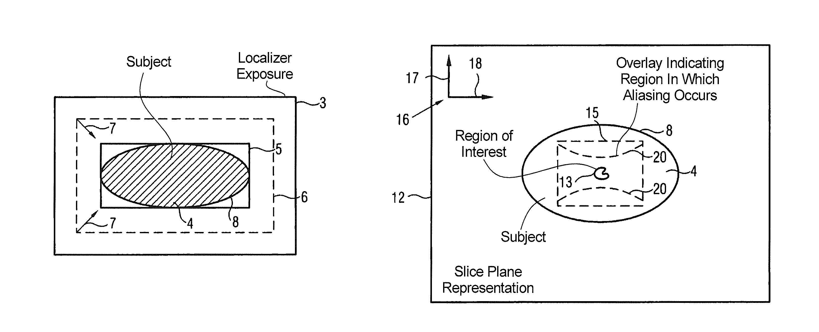
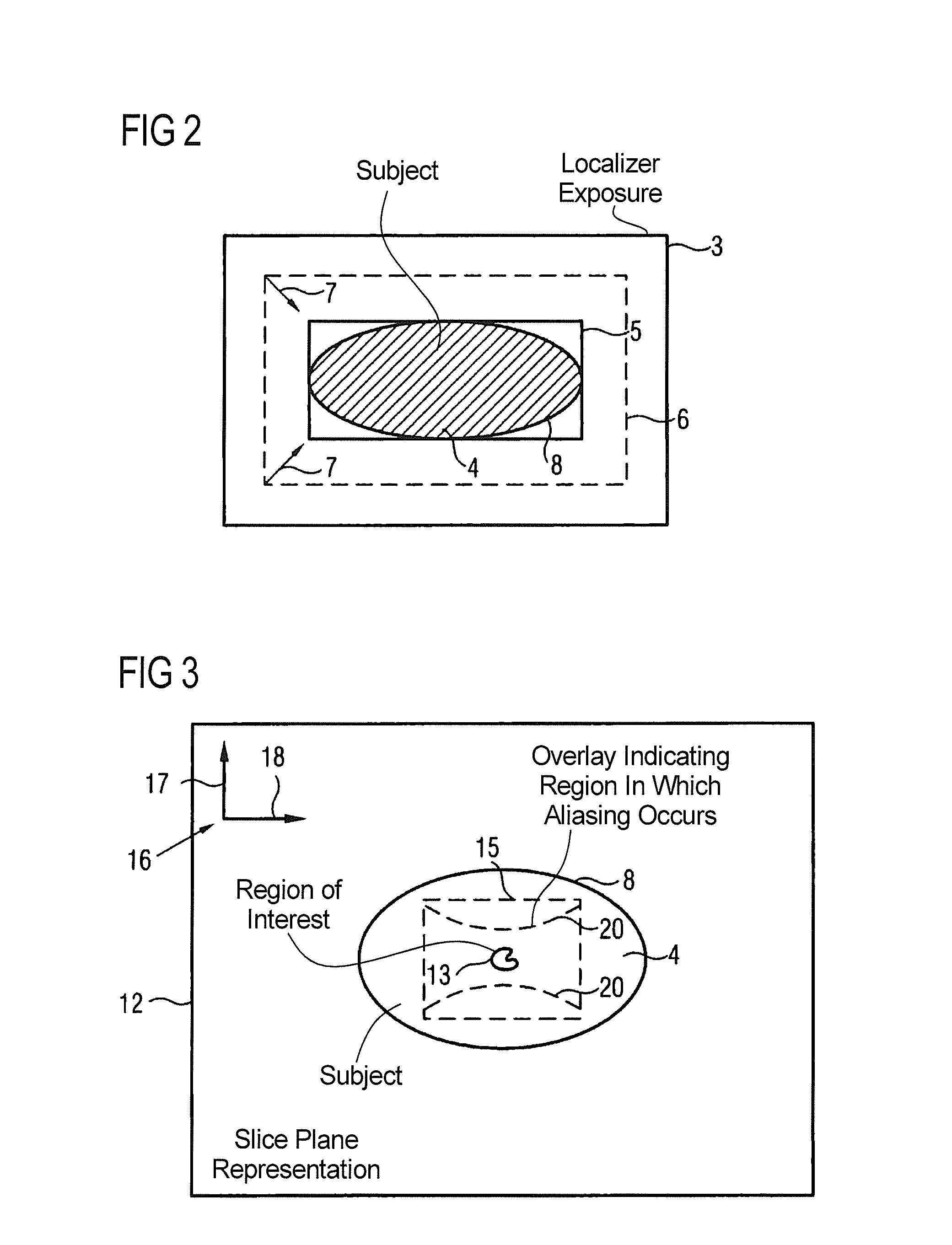
[0011]The basis of this method is thus to supply the system (for an automatic selection) or the user (for a manual selection) with patient-dependent prior information in order to enable a determination of the field of view to be made as optimally as possible, in particular with regard to the phase coding direction and / or the extent of the field of view in the phase coding direction. According to the invention, the localizer exposures that are acquired anyway in the typical workflow in magnetic resonance devices are used in order to obtain aliasing information, ultimately information about the extent of the subject at least in the area of the region of interest. A geometric shape is approximated as closely as possible to the surface of the subject that is visible in the localizer exposures while taking into account specific minimization criteria, or to determine the surface of the subject as optimally as possible and process this further if necessary. This aliasing information can be used in order to determine how far aliasing occurs in specific directions in specific dimensions of the field of view, which information can advantageously be used for assistance in the manual input of a field of view or even for automatic determination of the field of view. An improved (in particular smaller) field of view which entails a whole series of advantages is consequently defined via the method according to the invention, even in the phase coding direction. It is thus possible for the measurements to be significantly accelerated, but this gained measurement time can alternatively be “given up” in order to achieve a higher resolution or a better signal-to-noise ratio. In addition, the resolution in the image acquisition is adapted using the size of the field of view, in particular a maximum size of a field of view. With the method according to the invention, it is thus possible to determine an individual field of view for every slice plane given multiple slice planes. A slice plane-dependent field of view that is optimized in all of these slice planes represents an additional improvement and likewise leads to an acceleration of the measurements or even to a possible improvement of the image quality. The advantage gained by the improved field of view per slice plane thus can be realized in image quality, both for acceleration of the measurement and for a maintained measurement time, wherein an increased signal-to-noise ratio can be obtained.
[0018]In a further embodiment of the method according to the invention, however, it is not necessary for the user to have to mark the field of view in a representation. In this largely automated second embodiment of the method according to the invention, an aliasing-free, desired area (in particular encompassing the region) is selected to determine the phase coding direction and / or the extent of the field of view in the phase coding direction, whereupon the phase coding direction and / or the extent of the field of view in the phase coding direction is automatically determined from this area under consideration of the aliasing information. The method according to the invention thus does not require the details of k-space scanning to be used in an automatic determination based on the aliasing information (as was conventional), and thus allows a more intuitive focus to be made on the diagnostically useful region that is ultimately also to be determined. Given a manual or semi-automatic embodiment, the user must accordingly merely decide which area should be free of aliasing in this case, without having to be concerned about these artifacts and the underlying physics. The method is accordingly designed more simply and intuitively in this way.
[0026]The method according to the invention can also be advantageously applied in regard to a technique what is known as the “phase oversampling method”. Phase oversampling means that a field of view is used that encompasses the entire subject so that there is no aliasing, with data outside of a narrower field of view being discarded after the acquisition. In the framework of the method according to the invention, image data exhibiting aliasing in the image exposure can be determined and discarded under consideration of the aliasing information. In such an embodiment, however, the method according to the invention is already advantageous from the outset, to the effect that the dimensions of the subject can be taken into account for determination of this expanded field of view, such that this can also be shrunk.

Problems solved by technology

In the acquisition of image data with a magnetic resonance device, a number of artifacts are known that can occur when the image acquisition parameters are not ideally selected.
Such artifacts can occur in the partition direction even if no slice selection pulse is used, but is barely possible in practice.
Uncertainties and consequently measurements of images with aliasing in regions to be diagnosed can occur in the case of less well-trained personnel or less experienced personnel, such that the image acquisitions must be repeated.
This therefore leads to the situation that the user is not expected to input the field of view for every single slice (in particular in the phase coding direction) nor the position in the slice plane.
This is time-consuming and requires the acquisition of a plurality of additional measurement data.
In the methods available today, it is not possible for the user to adapt the field of view of a slice stack or of all slice planes of a protocol individually.
Although isolated measurements are known in which slices are measured with a different field of view in different protocols, such a procedure significantly lengthens the examination, in particular when these are measurements in which a patient must hold his breath.

Method used


Image

  • Method for image data acquisition with a magnetic resonance device
  • Method for image data acquisition with a magnetic resonance device
  • Method for image data acquisition with a magnetic resonance device

Examples


Embodiment Construction

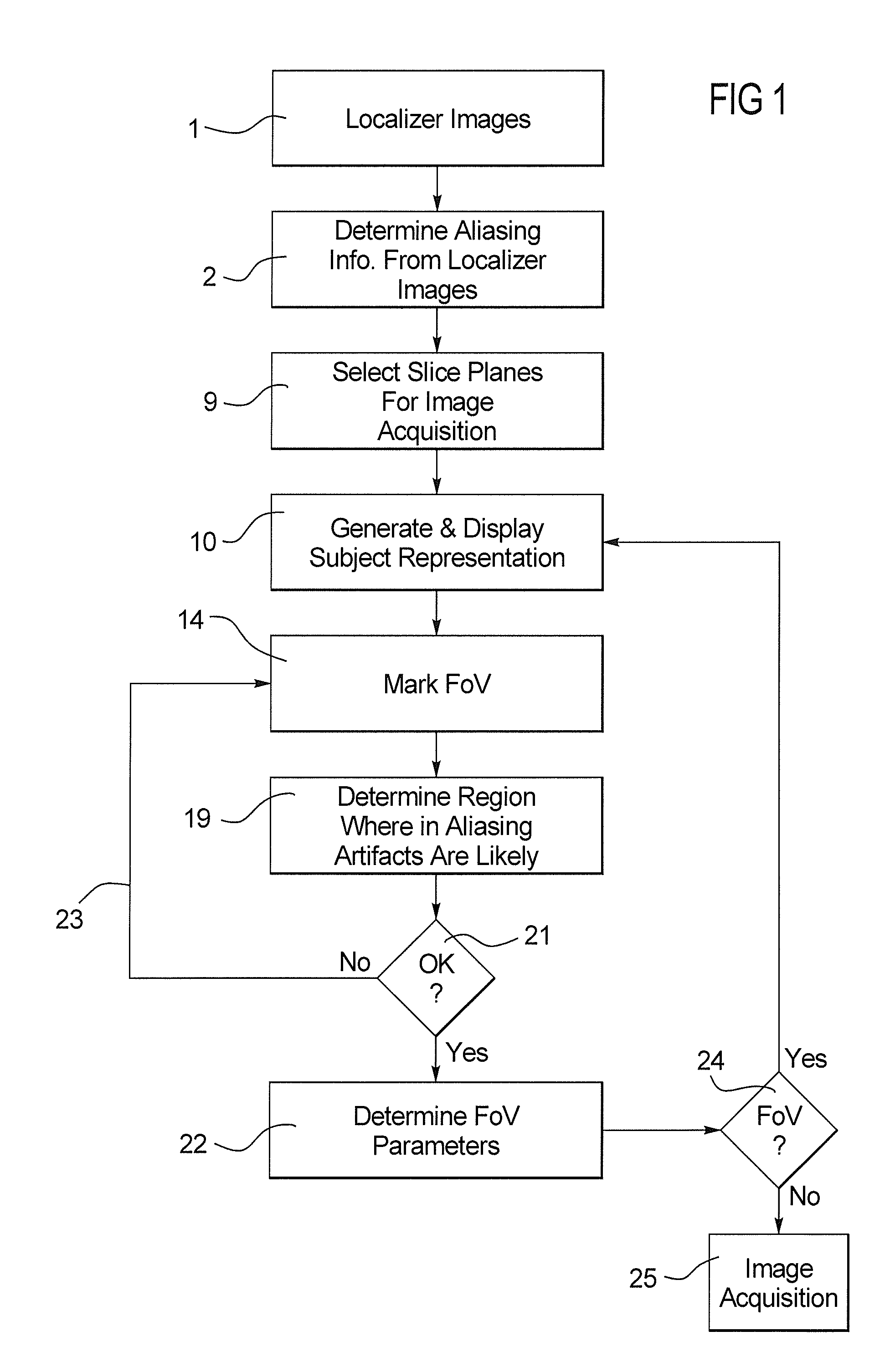
[0033]FIG. 1 shows a flowchart of a first embodiment of the method according to the invention. In a first step 1, a set of localizer exposures of a subject, which should later be the subject matter of an image acquisition with a magnetic resonance device, is initially generated, wherein in particular a region of interest should be acquired. Localizer exposures are already well known and do not need to be explained in detail herein.

[0034]In step 2 of the method according to the invention, aliasing information is determined from the localizer exposures. This information essentially reflects which dimensions the subject has and, correspondingly, how and where aliasing is to be expected. The aliasing information is thus subject-specific and is stored in the magnetic resonance device for the duration of the examination after its determination. In principle, two variants for the determination of said information are conceivable in the framework of the method according to the invention.

[00...


PUM


Abstract

In a method for image data acquisition of a region of interest in a subject with a magnetic resonance device, wherein, to establish the field of view, a minimal geometric shape encompassing the subject to be acquired and / or the surface of the subject is determined automatically from previously acquired localizer exposures as aliasing information for each exposure, at least one slice plane is determined for the acquisition of the region, and the phase coding direction and / or the extent of the field of view in the phase coding direction is determined for every slice plane using the aliasing information.

Description

BACKGROUND OF THE INVENTION[0001]1. Field of the Invention[0002]The present invention concerns a method for image data acquisition of a region of interest in a subject with a magnetic resonance device.[0003]2. Description of the Prior Art[0004]In the acquisition of image data with a magnetic resonance device, a number of artifacts are known that can occur when the image acquisition parameters are not ideally selected. In particular, an artifact known as aliasing can occur with regard to the determination of a field of view (FoV). This occurs when a field of view was selected in the phase coding direction so that a portion of the subject to be acquired (for example a patient body) is arranged outside of the field of view. Such artifacts can occur in the partition direction even if no slice selection pulse is used, but is barely possible in practice. The field of view in the phase coding direction (and possibly in the partition direction) is accordingly not selected based on the diagn...

Claims


Application Information

Patent Timeline
Patent Type & Authority Patents(United States)
IPC IPC(8): G01V3/00
CPCG01R33/4833G01R33/543G01R33/5608
Inventor GRIMME, ANDREASGUEHRING, JENSJOLLY, MARIE-PIERRESCHMIDT, MICHAELASPEIER, PETER
Owner SIEMENS HEALTHCARE GMBH
Learn More