
Efficient solar energy collector

a solar energy collector and solar energy technology, applied in solar heat systems, solar thermal energy generation, light and heating equipment, etc., can solve the problems of poor conversion efficiency of all known devices, and the efficient system is relatively unavailable for wide distribution to many developing countries, and achieves high conversion of sunlight to hea

Inactive Publication Date: 2019-10-22
LISS AARON
View PDF8 Cites 0 Cited by
  • Summary
  • Abstract
  • Description
  • Claims
  • Application Information

AI Technical Summary

Benefits of technology

[0005]The invention relates to a solar conversion system, comprising solar focusing means for focusing solar energy incident thereon into a solar beam, said solar beam at its smallest cross section having a cross section substantially less than the cross section of the solar focusing means, container means to retain a liquid to be heated by solar energy, said container means having an opening approximately the size of the smallest cross section of the solar beam, positioning means operable for positioning said focusing means so that the smallest cross section of said solar beam is located at the opening so that substantially all of the solar beam enters into said container, dispersing means positioned in said container in the path of said solar beam operable to disperse the solar beam in said container, thereby reducing the amount of reflected solar beam exiting the opening.
[0007]The invention enables a simple focusing system such as a Fresnel lens the size of a letter to serve effectively. Hence, the invention is extremely inexpensive, highly portable, and easily implemented.

Problems solved by technology

There are a multitude of devices to capture solar energy in some useful way; however, it is well known that all known devices suffer from relatively poor conversion efficiency.
It is rare that a conversion of solar energy to another form of energy such as electricity, or heat is greater than about 50%, and the higher efficiency requires highly specialized equipment, thereby making an efficient system relatively unavailable for wide distribution to many developing countries.

Method used


Image

  • Efficient solar energy collector
  • Efficient solar energy collector

Examples


Embodiment Construction

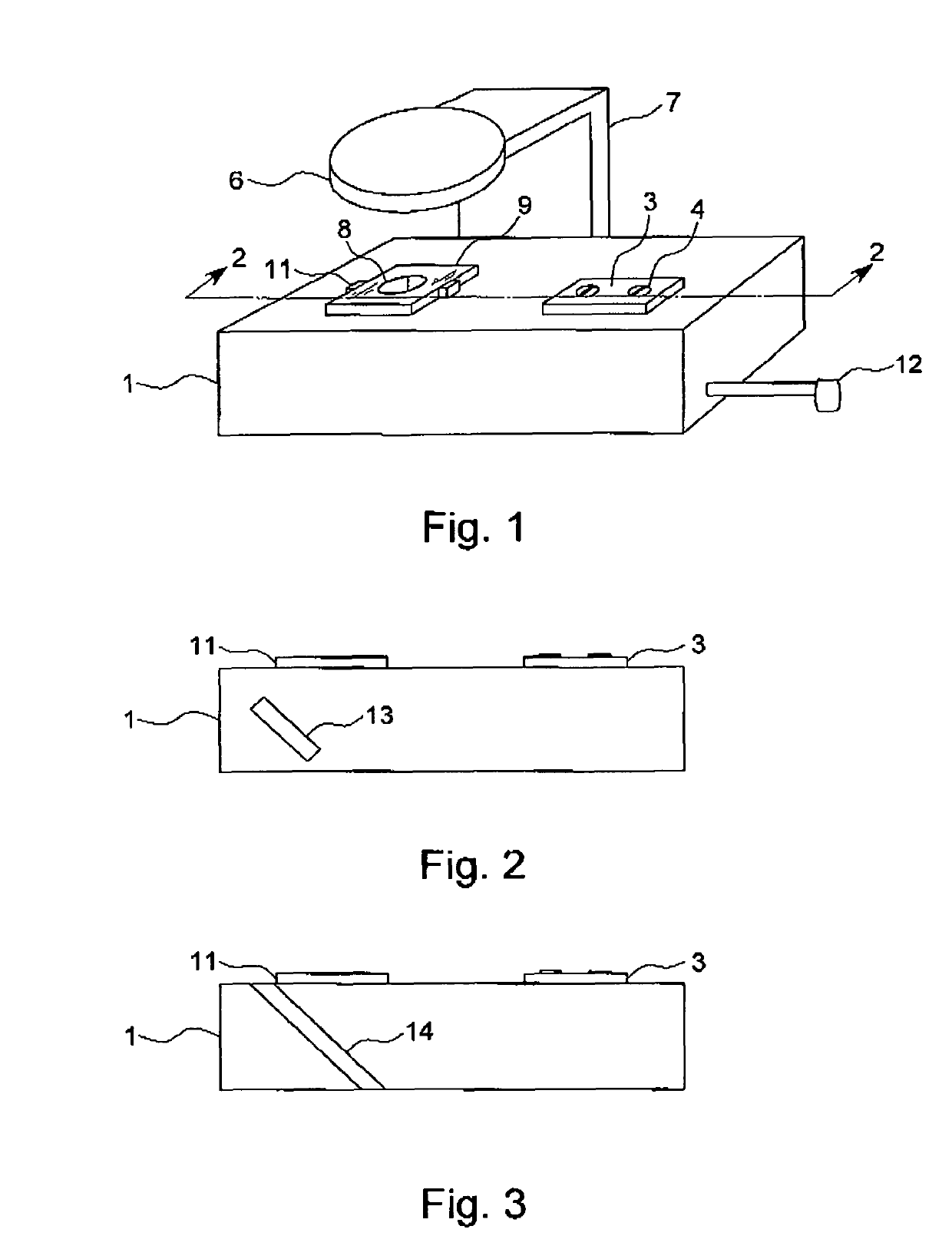
[0016]FIG. 1 shows a perspective view of an embodiment of the invention. The container 1 is a rectangular parallelepiped; however, container 1 is not limited to this shape. Plate 3 is removable to expose an opening to allow a liquid (not shown) to be placed into the container 1. Typically, the substance can be water, or soup, or some other liquid to be heated, or cooked. The plate 3 is maintained closed with screws 4, but other convenient arrangements can be used.

[0017]Focusing means 6 such as a magnifying glass, a Fresnel lens, or the like is to focus sunlight. The focusing means 6 is connected to support means 7 for holding the focusing means 6 in a desirable position for focusing sunlight onto the aperture 8. The support means 7 can be a conventional design suitable for the operations for this invention. The support means 7 can be hand held, if necessary.

[0018]As used herein, the “cross section” of the focusing means 6 is the area of the incident sunlight on the focusing means 6 ...


PUM


Abstract

The invention relates to a solar conversion system, comprising solar focusing means for focusing solar energy incident thereon into a solar beam, said solar beam at its smallest cross section having a cross section less than about ten percent of the cross section of the solar focusing means, container means to retain a fluid to be heated by solar energy, said container means having an opening approximately the size of the smallest cross section of the solar beam, positioning means operable for positioning said focusing means so that the smallest cross section of said solar beam is located at the opening so that substantially all of the solar beam enters into said container, dispersing means positioned in said container in the path of said solar beam operable to disperse the solar beam in said container, thereby reducing the amount of reflected solar beam exiting the opening.

Description

BACKGROUND OF THE INVENTION[0001]The present invention relates to an efficient solar energy conversion system, and particularly to a simple system for converting solar energy to heat suitable for creating heat suitable for cooking food, driving an engine, to create electricity, providing hot water for many applications, and other uses.[0002]From early times of mankind, it has been recognized that solar energy is an abundant source of energy. The discovery of the magnifying glass was a breakthrough on concentrating solar energy for igniting a fire. The discovery of methods for the conversion solar energy into electricity was another breakthrough.[0003]There are a multitude of devices to capture solar energy in some useful way; however, it is well known that all known devices suffer from relatively poor conversion efficiency. Generally, the efficiency of converting solar energy is less than about 25%. It is rare that a conversion of solar energy to another form of energy such as elect...

Claims


Application Information

Patent Timeline
Patent Type & Authority Patents(United States)
IPC IPC(8): F24S20/30F24S20/20F24S23/00
CPCF24S23/00F24S20/30F24S20/20F24S23/30Y02E10/44
Inventor LISS, AARON
Owner LISS AARON
Learn More