
Heat pipe with non-condensable gas

a heat pipe and non-condensable technology, applied in the field of heat pipes, can solve the problems that the electrical components cannot maximize their work efficiency, and achieve the effect of reducing the contact area, reducing the conduction efficiency of the heat pipe, and achieving the desired work efficiency

Active Publication Date: 2020-02-25
CELSIA TECH TAIWAN INC
View PDF5 Cites 0 Cited by
  • Summary
  • Abstract
  • Description
  • Claims
  • Application Information

AI Technical Summary

Benefits of technology

The patent describes a heat pipe that uses a non-condensable gas and a protrusion on its surface to improve the efficiency of heat conduction. The heat pipe is designed to work at a specific temperature range, reducing the conduction efficiency and allowing the heat-generating electronic component to achieve better work efficiency. This results in improved practicality and reduced energy waste.

Problems solved by technology

However, in a special using environment (such as a very cold environment), the good thermal conduction efficiency of the heat pipe may cause a failure for the electronic component to reach an appropriate working temperature, so that the electronic component will be unable to maximize its work efficiency.

Method used


Image

  • Heat pipe with non-condensable gas
  • Heat pipe with non-condensable gas
  • Heat pipe with non-condensable gas

Examples


Embodiment Construction

The technical contents of this disclosure will become apparent with the detailed description of preferred embodiments accompanied with the illustration of related drawings as follows. It is noteworthy that same numerals are used for representing same respective elements in the drawings.

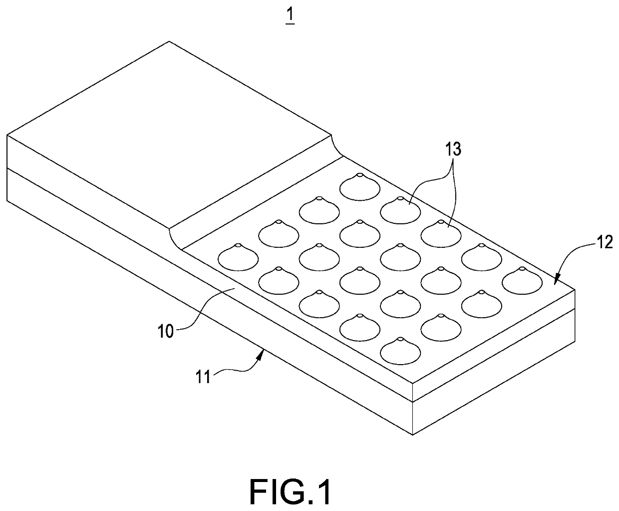
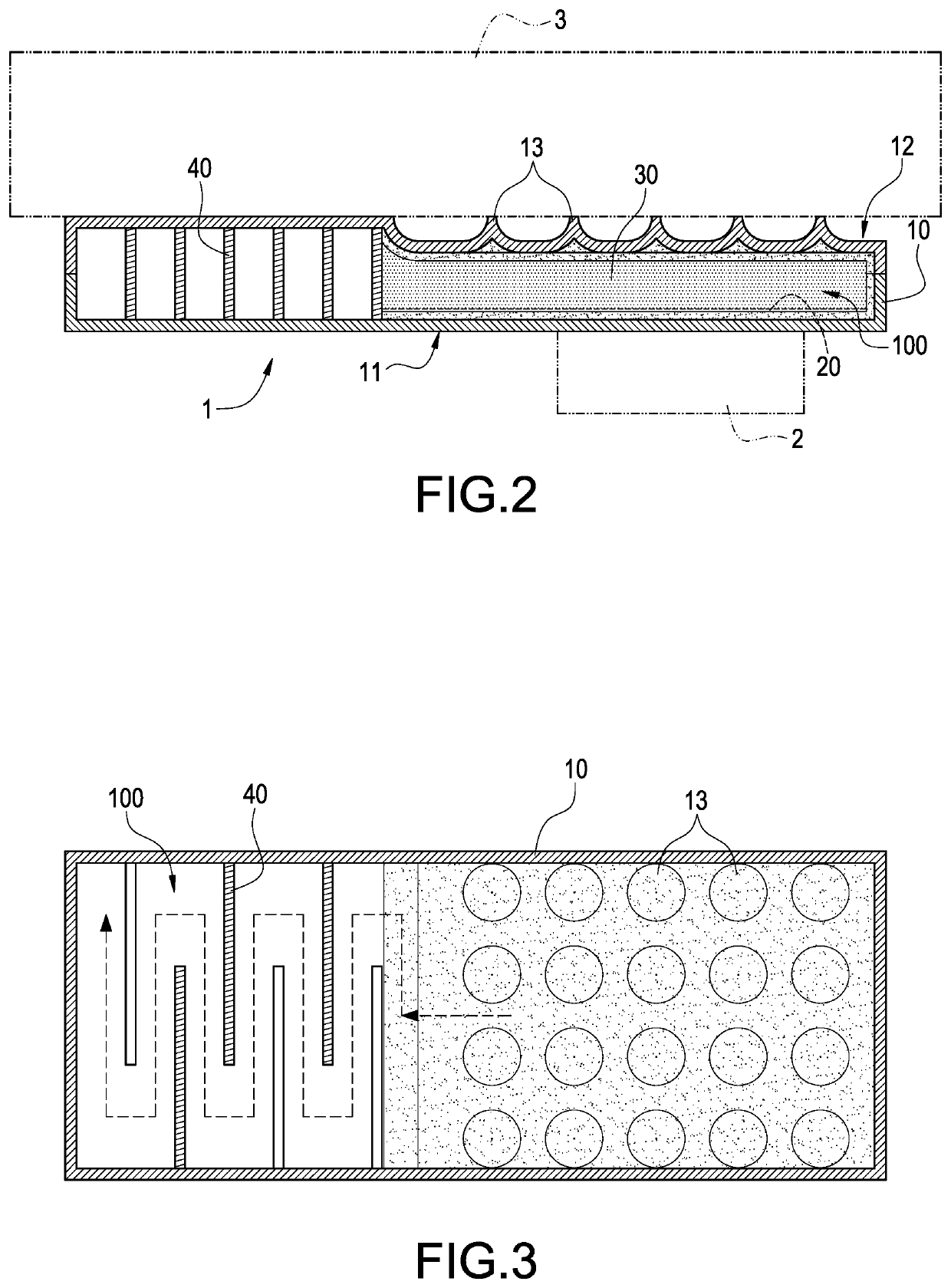
With reference to FIGS. 1 to 3 for a perspective view, a schematic view and a cross-sectional view of a heat pipe with a non-condensable gas of this disclosure respectively, FIGS. 1 and 2 show that the heat pipe with a non-condensable gas 1 is used for cooling a heat-generating electronic component 2. Preferably, the heat pipe 1 is combined with a radiator 3. In a preferred embodiment of this disclosure, the radiator 3 is a cooling fin module.

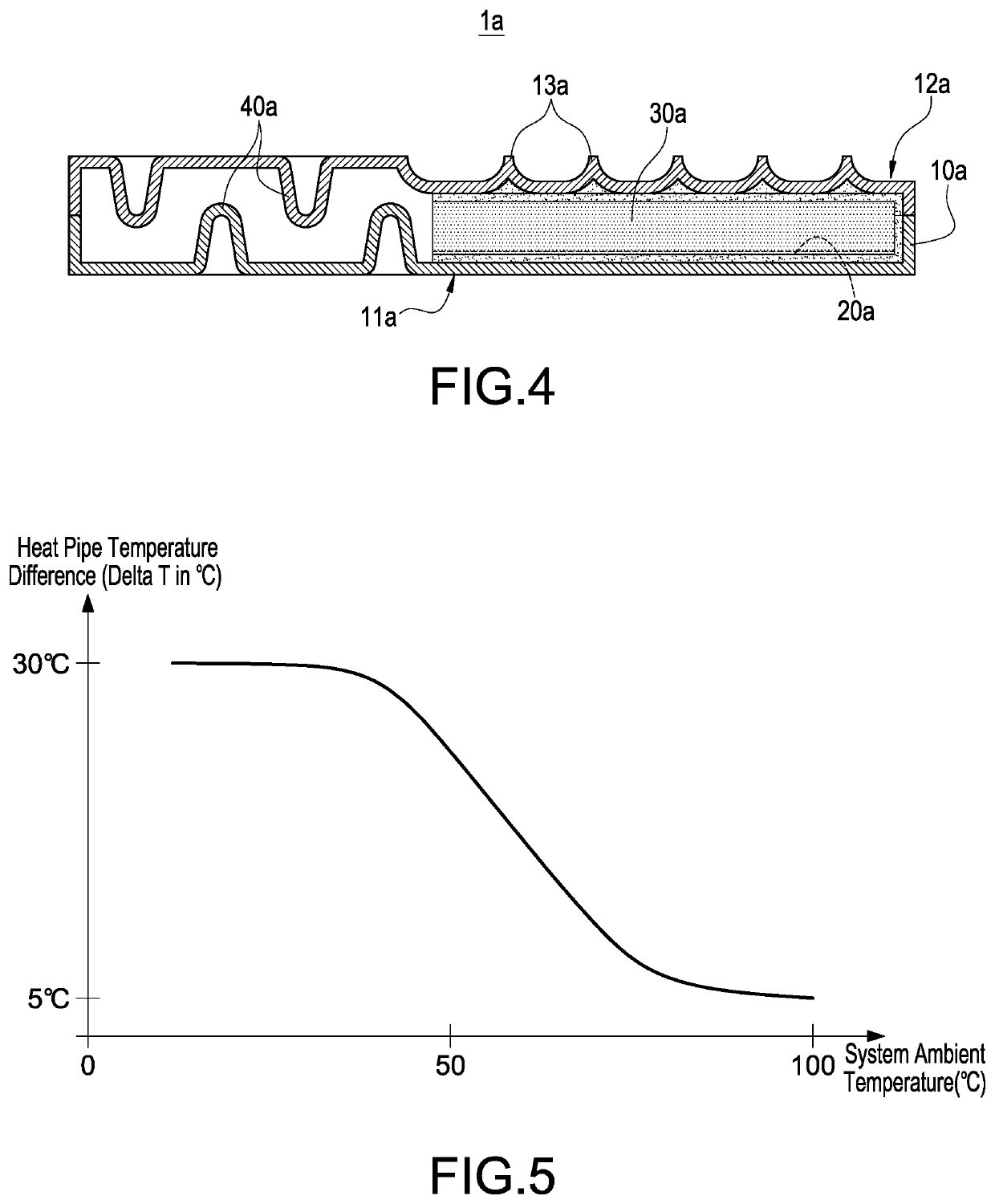
In FIGS. 2 and 3, the heat pipe 1 of this preferred embodiment comprises a thermal conductor 10, a working fluid 20, and a non-condensable gas 30, wherein the working fluid 20 and the non-condensable gas 30 are filled into the thermal conductor 10. The structure ...


PUM


Abstract

A heat pipe with a non-condensable gas includes a thermal conductor, and a working fluid and a non-condensable gas filled into a hollow chamber of the thermal conductor, and the thermal conductor has a heat-absorbing side attached to a heat-generating electronic component and an exothermal side attached to a radiator, and the exothermal side has at least one protrusion, and the exothermal side with the protrusion can reduce the contact area with the radiator, and the heat pipe lowers the conduction efficiency by the non-condensable gas and the protrusion, so as to achieve a work efficiency of the heat-generating electronic component in an operation within a working temperature range.

Description

BACKGROUND OF THE INVENTION1. Technical FieldThis disclosure generally relates to the field of heat pipes, and more particularly to a heat pipe with a non-condensable gas.2. Description of Related ArtIn the working principle of a general heat pipe, the heat pipe provides an internal vacuum environment filled with a working fluid and produces a phase change when the working fluid is heated, so as to transfer heat. After the working fluid is cooled, the working fluid returns to its liquid state and backflows for recycle and reuse. An evaporating end surface of the heat pipe is attached to a surface of a heat-generating electronic component, so that the heat produced by the electronic component may be absorbed by the evaporating end surface of the heat pipe and then conducted to the radiator through the heat pipe to achieve the heat dissipation effect.In a conventional heat pipe, the internal structure is situated at a vacuum status, and no non-condensable gas is in the heat pipe, so t...

Claims


Application Information

Patent Timeline
Patent Type & Authority Patents(United States)
IPC IPC(8): F28D15/02H05K7/20
CPCF28D15/0233H05K7/202H05K7/20127F28D15/0275H05K7/20336F28F3/042F28F3/044F28F3/046F28D1/035F28D1/0383
Inventor MEYER, IV, GEORGE A.SUN, CHIEN-HUNG
Owner CELSIA TECH TAIWAN INC
Learn More