
Pyranometer with forced airflow

a technology of pyranometer and forced airflow, which is applied in the field of pyranometer, can solve the problems of reducing the “data availability”, i.e. significant source of measurement uncertainty, and zero offset, and achieve the effect of increasing body weight and reducing offsets

Active Publication Date: 2020-01-28
HUKSEFLUX HLDG BV
View PDF8 Cites 0 Cited by
  • Summary
  • Abstract
  • Description
  • Claims
  • Application Information

AI Technical Summary

Benefits of technology

The invention is about a new kind of detector that uses a closed housing with a built-in ventilator to keep it warm and clean. This makes it a compact and simple device. The detector is connected to the outer part of the housing, so it is always warm and clear of snow or ice. The detector is also designed to use different gases and can be combined with other measures to prevent zero offsets, such as increasing its body weight or insulating it from contact with the ambient air. Overall, this new detector makes it easier to measure the temperature of the environment and collect accurate data.

Problems solved by technology

Using thermal-electric sensors (as opposed to photo-electric sensors), zero offsets, i.e. signals not related to the quantity to be measured, are a significant source of measurement uncertainty.
Deposited water on pyranometer domes leads to unpredictable and potentially very large but non-quantifiable errors; it reduces the “data availability”.
Deposition of rain and snow are quite common, but this usually goes together with cloudy conditions under which the measurement errors are small.
Deposition of dew or frost on dome in the early morning regularly causes large errors.
A dry dome also is unattractive for dust to stick to.
Using traditional pyranometers, already at low power levels, where heating is not yet effective to prevent humidity from condensing on the instrument dome, the added zero offsets caused by direct heating are beyond the specification limits of the ISO 9060 standard.
Applying direct heating at higher power, for example to promote evaporation and sublimation or to melt snow or ice is possible, but creates still larger errors and therefore is not mentioned in any standard.

Method used


Image

  • Pyranometer with forced airflow
  • Pyranometer with forced airflow

Examples


Embodiment Construction

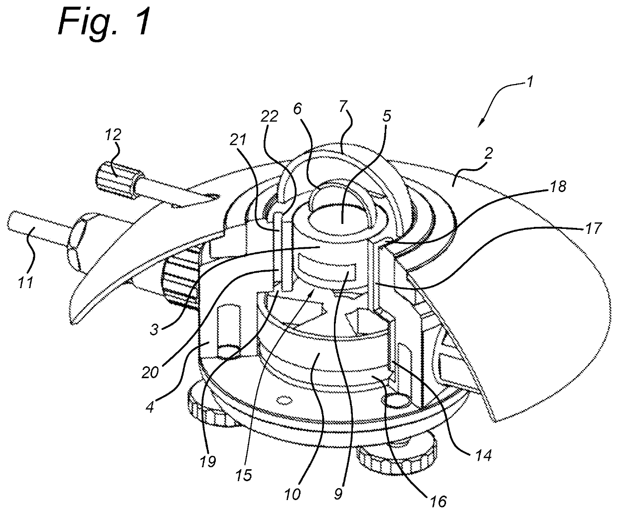
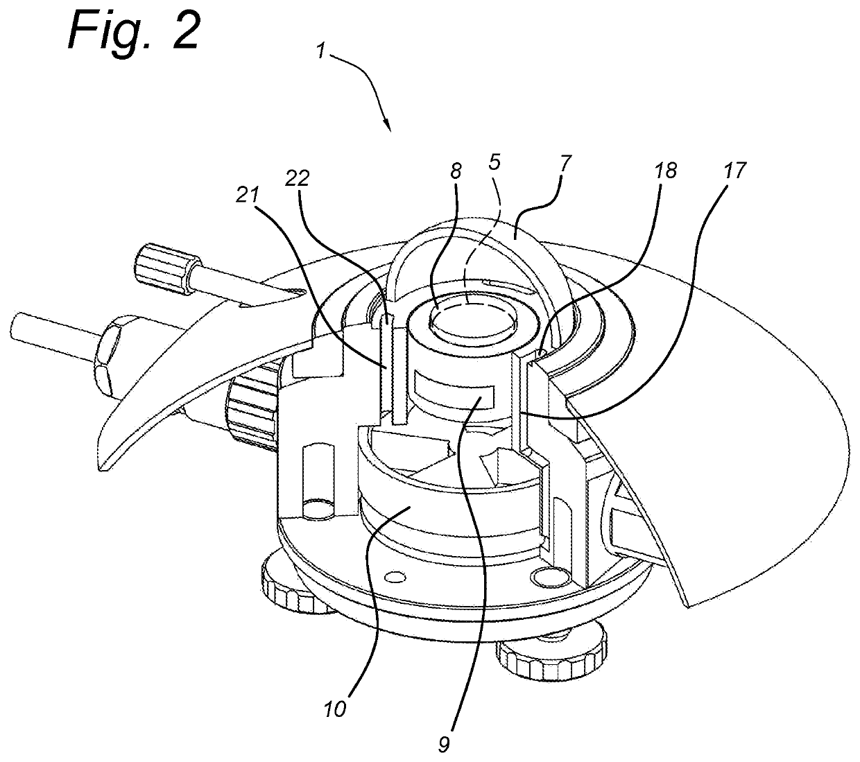
[0046]In the FIG. 1, a pyranometer 1 is shown with a substantially closed housing 2 encompassing a detector body 3, a cylindrical metal wall 4 and a thermal sensor 5. The sensor 5 is covered by an inner dome 6 in thermal contact with a top face of the body 3 and an outer dome 7 that is in thermal conducting contact with a top face of the detector wall 4.

[0047]Enclosed by the wall 4, a ventilator space 15 houses a mini ventilator 10, which may have a diameter of for instance 3.5 cm and a power of 0.5 W. A lower side 16 of the ventilator space 15 is in contact with an outlet 14 of air outlet duct 17 which has an inlet 18 in the space between the domes 6, 7. An upper side 19 of the ventilator space 15 is in contact with the inlet 20 of air supply duct 21 having its outlet 22 in the space between the domes 6, 7. The inlet 18 and outlet 22 are situated at diametrically opposed positions on the top face of the detector wall 4.

[0048]The internal ventilator 10 provides a closed circuit for ...


PUM

PropertyMeasurementUnit
poweraaaaaaaaaa
poweraaaaaaaaaa
dome temperatureaaaaaaaaaa

Abstract

Disclosed is a pyranometer with a housing, a sensor in the housing, an inner window and an outer dome-shaped window both overlying the sensor. An air inlet duct and an air outlet duct extend in the housing and end in a space confined by the outer window for passing air through the space, from the inlet duct to the outlet duct. The housing is substantially closed such that no outside air flows are allowed into the housing and includes a ventilator, the inlet duct being in fluid communication with a high pressure side of the ventilator, the outlet duct being in fluid communication with a low pressure side of the ventilator. The air blown into the space below the outer window is heated by the ventilator power and optionally by and added electrical heater.

Description

FIELD OF THE INVENTION[0001]The invention relates to a pyranometer with a housing, a thermo-electric sensor in said housing, an inner window and an outer dome-shaped window both windows overlying the sensor, an air inlet duct and an air outlet duct extending in the housing and ending in a space that is bounded by the outer window for passing air through said space, from the inlet duct to the outlet duct.BACKGROUND OF THE INVENTION[0002]Such a radiation detection device in the form of a pyranometer is known from U.S. Pat. No. 3,876,880. In this publication a pyranometer is described in which an external pump and heat exchanger provide a cooling air stream to the detector housing for cooling the inner and outer domes. In addition, an external blower directs an air stream across the domes for increasing the radiation measurement accuracy.[0003]It is commonly known in pyranometers (for instance model SR11, marketed by Hukseflux Thermal Sensors B.V., Delft, Netherlands) to utilize an inn...

Claims


Application Information

Patent Timeline
Patent Type & Authority Patents(United States)
IPC IPC(8): G01K1/00G01K13/00G01J5/04G01J1/42G01J5/02
CPCG01J5/042G01J1/4204G01J5/029G01J2001/4285G01J1/42G01J5/05G01J5/051
Inventor HOEKSEMA, ERIC RICHARDVAN DEN BOS, CORNELIS JAN
Owner HUKSEFLUX HLDG BV
Learn More