
Method for gallium nitride on diamond semiconductor wafer production

a technology of gallium nitride and semiconductor wafers, which is applied in the direction of semiconductor devices, semiconductor/solid-state device details, electrical equipment, etc., can solve the problems of high device junction temperature, hot or and less reliable devices, and conventional gan hemt technology (e.g. on sic, sapphire or si substrates) suffer from thermal bottleneck at the chip level, so as to minimize the thermal expansion mismatch between said gan layer and said diamond substrate.

Active Publication Date: 2020-01-07
BAE SYST INFORMATION & ELECTRONICS SYST INTEGRATION INC
View PDF7 Cites 1 Cited by
  • Summary
  • Abstract
  • Description
  • Claims
  • Application Information

AI Technical Summary

Benefits of technology

This approach enhances device performance and reliability by leveraging diamond's high thermal conductivity, reducing wafer bow, and minimizing stress, resulting in 3-5× higher power handling capability compared to GaN-on-SiC HEMT, enabling smaller, more efficient RF sources with reduced cooling and power requirements.

Problems solved by technology

Although the thermal resistance of many military high-power electronic components can be as large as that of the remaining elements of the system combined, spreaders, heatsinks or coldplates do not directly access the active region where heat is generated, and cannot materially affect the device junction temperature.
The conventional GaN HEMT technology (e.g. on SiC, sapphire or Si substrates) suffers from a thermal bottleneck at the chip level.
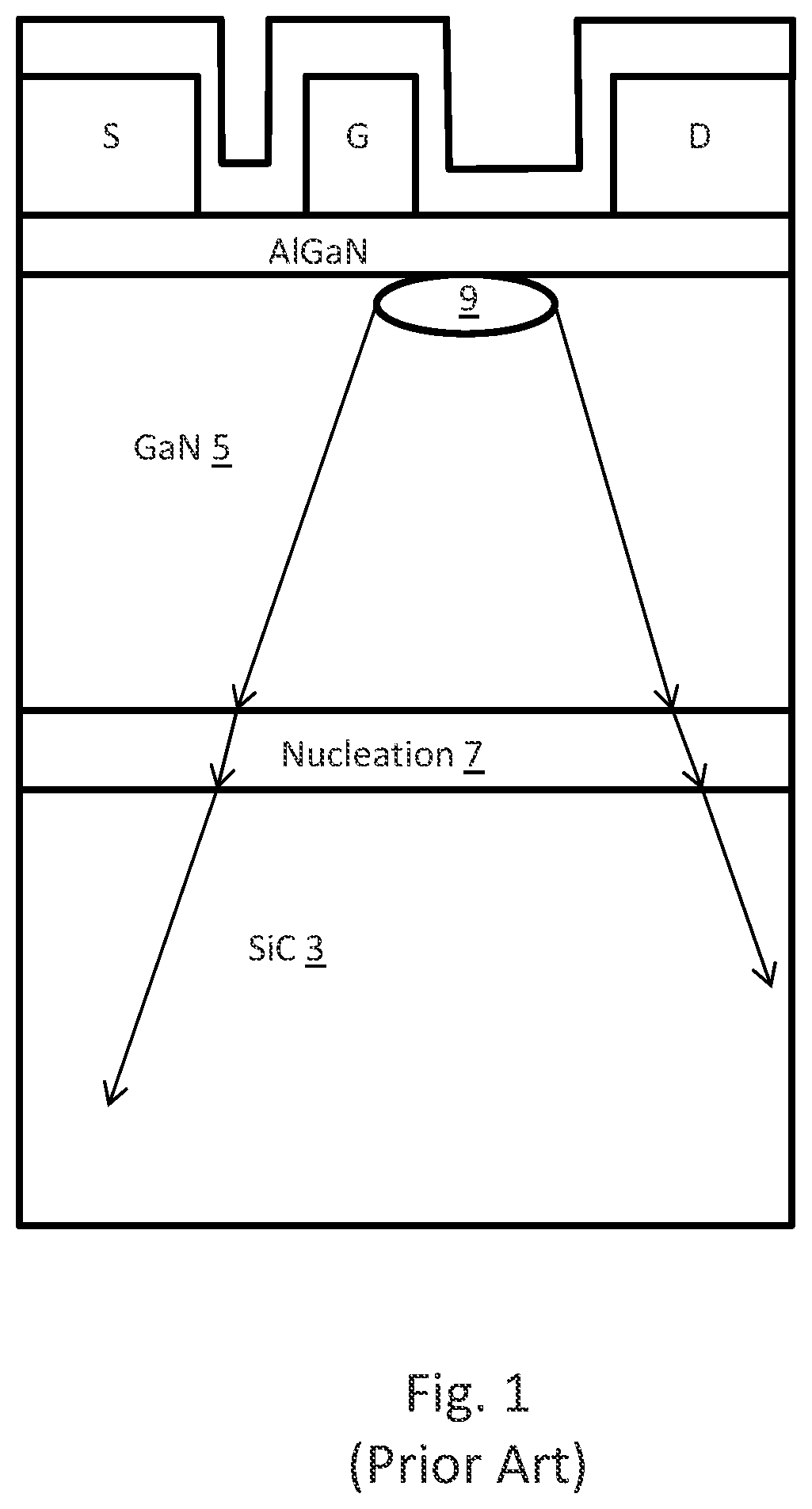
Heat generated from the hot spot in the conventional GaN HEMT will need to go through several microns of poor thermal conductivity GaN epitaxial layer and nucleation layers before reaching the substrate, making devices run hot or and less reliable.
The lack of an efficient thermal dissipation pathway results in high device junction temperature, which compromises both performance and reliability.
This makes the fabrication of devices and circuits on such a wafer very challenging.
The device reliability may also be affected with the extra epitaxial layer stress.
This process results in a number of disadvantages: a) The lower performance of GaN-on-Si as the starting epitaxial layer material results in lower GaN device performance, comparing to that of the industry standard GaN-on-SiC HEMT. b) The large wafer bow makes subsequent device processing difficult. c) High tensile stress in the GaN epitaxial film can lead to reduced device reliability. d) The device does not take the full advantage of the diamond high thermal conductivity due to the thick GaN epitaxial layer and buffer transition layers between the hot spot and the diamond substra

Method used


Image

  • Method for gallium nitride on diamond semiconductor wafer production
  • Method for gallium nitride on diamond semiconductor wafer production
  • Method for gallium nitride on diamond semiconductor wafer production

Examples


Embodiment Construction

[0043]A GaN-on-Diamond approach configured according to one embodiment uses low temperature bonding techniques (below 400 C) to attach diamond substrates to GaN layers. Mechanical stress due to thermal expansion mismatch between GaN and diamond is minimized, leading to smaller wafer bow, easier and higher yield wafer processing and improved device lifetime. Such embodiments also describe a method to uniformly reduce GaN epitaxial layer thickness to further improve device thermal property for higher performance and reliability.

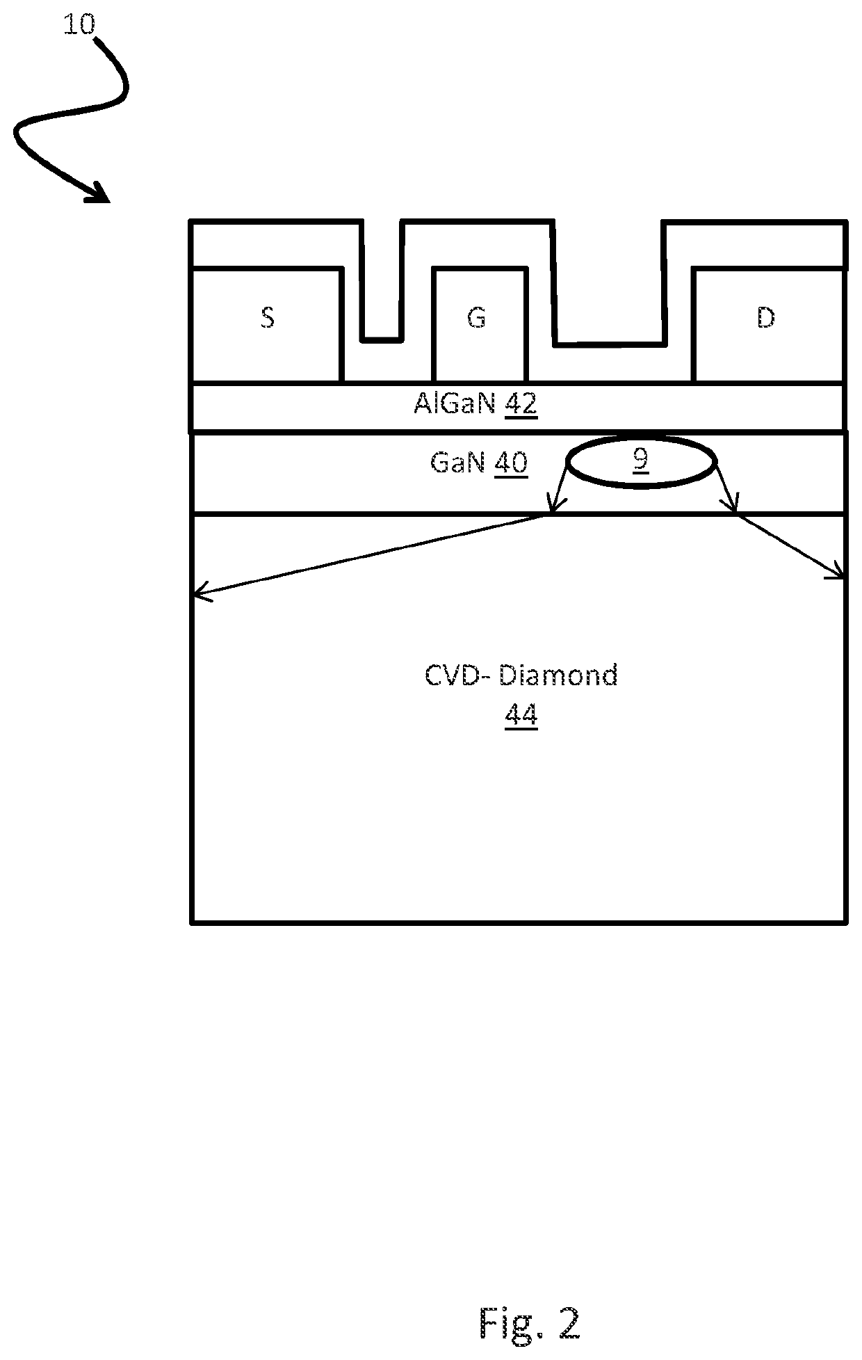
[0044]As illustrated in FIG. 1, a traditional GaN on SiC HEMT includes a thick GaN layer 5 and a nucleation layer 7. Heat from a hotspot 9 on a conventional must travel through the GaN layer and the nucleation layer before it begins to dissipate in the SiC layer 3. As seen in FIG. 2, embodiments of the present invention provide a wafer which includes a thinner GaN layer in comparison. In such an embodiment, the final GaN-on-diamond wafer 10 does not have a nucl...


PUM

PropertyMeasurementUnit
temperatureaaaaaaaaaa
thickaaaaaaaaaa
temperatureaaaaaaaaaa

Abstract

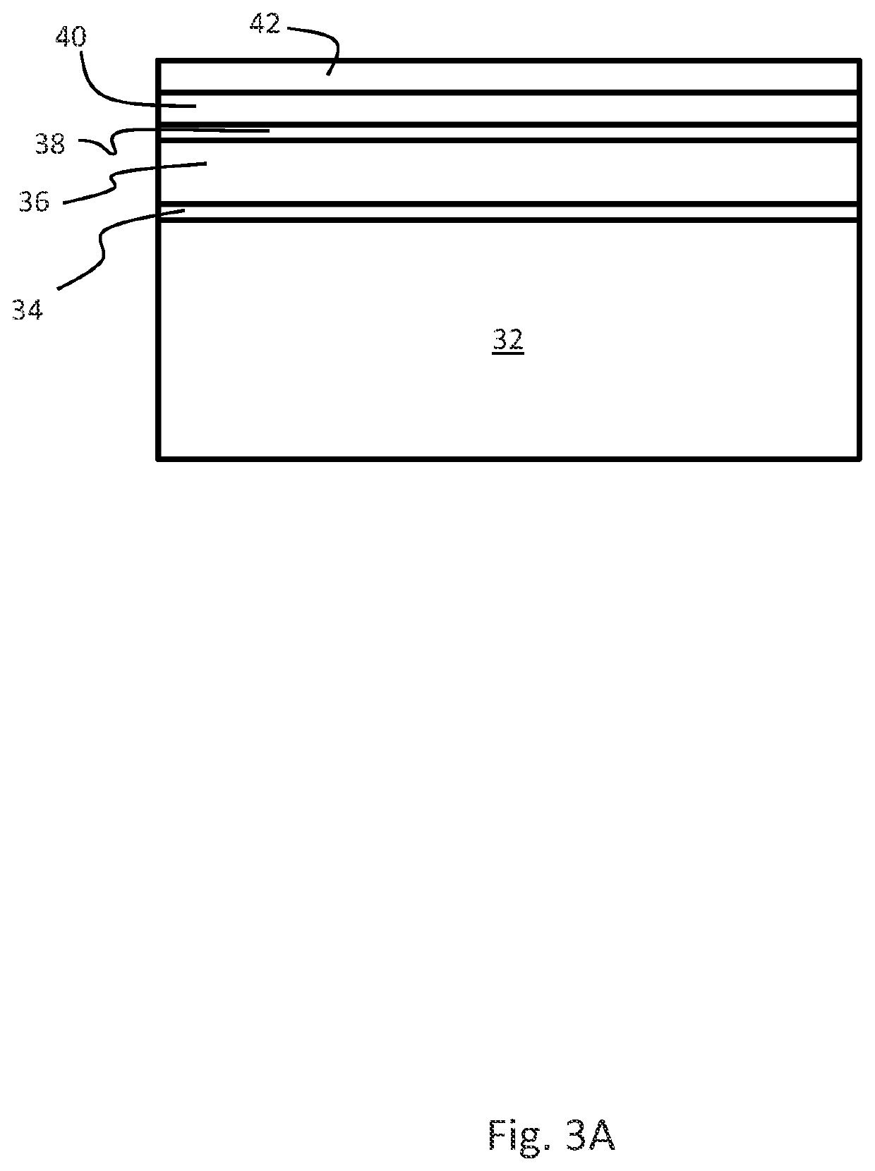
A GaN on diamond wafer and method for manufacturing the same is provided. The method comprising: disposing a GaN device or wafer on a substrate, having a nucleation layer disposed between the substrate and a GaN layer; affixing the device to a handling wafer; removing the substrate and substantially all the nucleation layer; and bonding the GaN layer to a diamond substrate.

Description

RELATED APPLICATIONS[0001]This application claims the benefit of U.S. Provisional Applications No. 62 / 024,774, filed Jul. 15, 2014. This application is herein incorporated by reference in its entirety for all purposes.STATEMENT OF GOVERNMENT INTEREST[0002]This invention was made with United States Government support under Contract No. FA8650-09-C-5404 awarded by the United States Air Force and W31P4Q-12-C-0019 awarded by the United States Department of the Army. The United States Government has certain rights in this invention.FIELD OF THE INVENTION[0003]The invention relates to semiconductor fabrication, and more specifically, the fabrication of GaN wafers with high thermal conductivity substrates.BACKGROUND OF THE INVENTION[0004]In most modern military electronic systems, the electronic device is typically the warmest element in the system. Although the thermal resistance of many military high-power electronic components can be as large as that of the remaining elements of the sys...

Claims


Application Information

Patent Timeline
Patent Type & Authority Patents(United States)
IPC IPC(8): H01L29/66H01L29/778H01L21/02H01L21/768H01L27/12H01L23/373H01L21/20H01L21/683H01L29/20H01L21/04
CPCH01L21/6835H01L29/66431H01L21/76876H01L21/0254H01L29/778H01L21/2007H01L29/7786H01L23/3732H01L27/1266H01L2221/68327H01L21/0475H01L21/2011H01L29/2003
Inventor CHU, KANINCHAO, PANE CHANECREAMER, CARLTON T
Owner BAE SYST INFORMATION & ELECTRONICS SYST INTEGRATION INC
Learn More