Apparatus and method for an electric power supply with changeable electric connectivity between battery modules

a technology of electric power supply and battery module, which is applied in the direction of battery/fuel cell control arrangement, secondary cell servicing/maintenance, safety/protection circuit, etc., can solve the problems of not being compatible with the ac power the machine needs, assumed to be a major safety risk, and not being able to operate directly with the electricity provided by the available one or more energy source elements and/or one or more electrical storage elements, etc., to achieve the effect of reducing cos

Active Publication Date: 2019-10-15
DR ING H C F PORSCHE AG
View PDF16 Cites 31 Cited by
  • Summary
  • Abstract
  • Description
  • Claims
  • Application Information

AI Technical Summary

Benefits of technology

[0112]The advantage of the invention is that such safety measures can be implemented on the cell or battery module level and do not necessarily have to involve a central controller. Furthermore, the implementation can be very simplistic without the need of microcontrollers or similar complex digital or mixed-signal electronic components. Thus, response times can be minimized for a fast action to counteract critical conditions, such as battery cells that may potentially undergo a thermal runaway, before it is unstoppable or spreads to other cells.

Problems solved by technology

Whereas earlier electric cars preferably used DC motors as electric machine, more recent vehicles implement multiphase AC motors, e.g., synchronous machines and induction machines, and can typically not be operated directly with the electricity provided by the available one or more energy source elements and / or one or more electrical storage elements.
For instance, most electric storage elements use DC voltages, which is not compatible to the AC power the machine requires.
As the battery pack in conventional applications is hard-wired and therefore presents the peak voltage at all times, also while the machine is not operated and / or the so system turned off, it is assumed to be a major safety risk and complicates the work of rescue teams in case of accidents.
The charging unit usually incorporates a converter, which (a) increases cost, (b) requires space, and (c) increases weight.
However, this low-voltage battery (usually lead-acid technology) adds additional weight and cost.

Method used


Image

  • Apparatus and method for an electric power supply with changeable electric connectivity between battery modules
  • Apparatus and method for an electric power supply with changeable electric connectivity between battery modules
  • Apparatus and method for an electric power supply with changeable electric connectivity between battery modules

Examples


Embodiment Construction

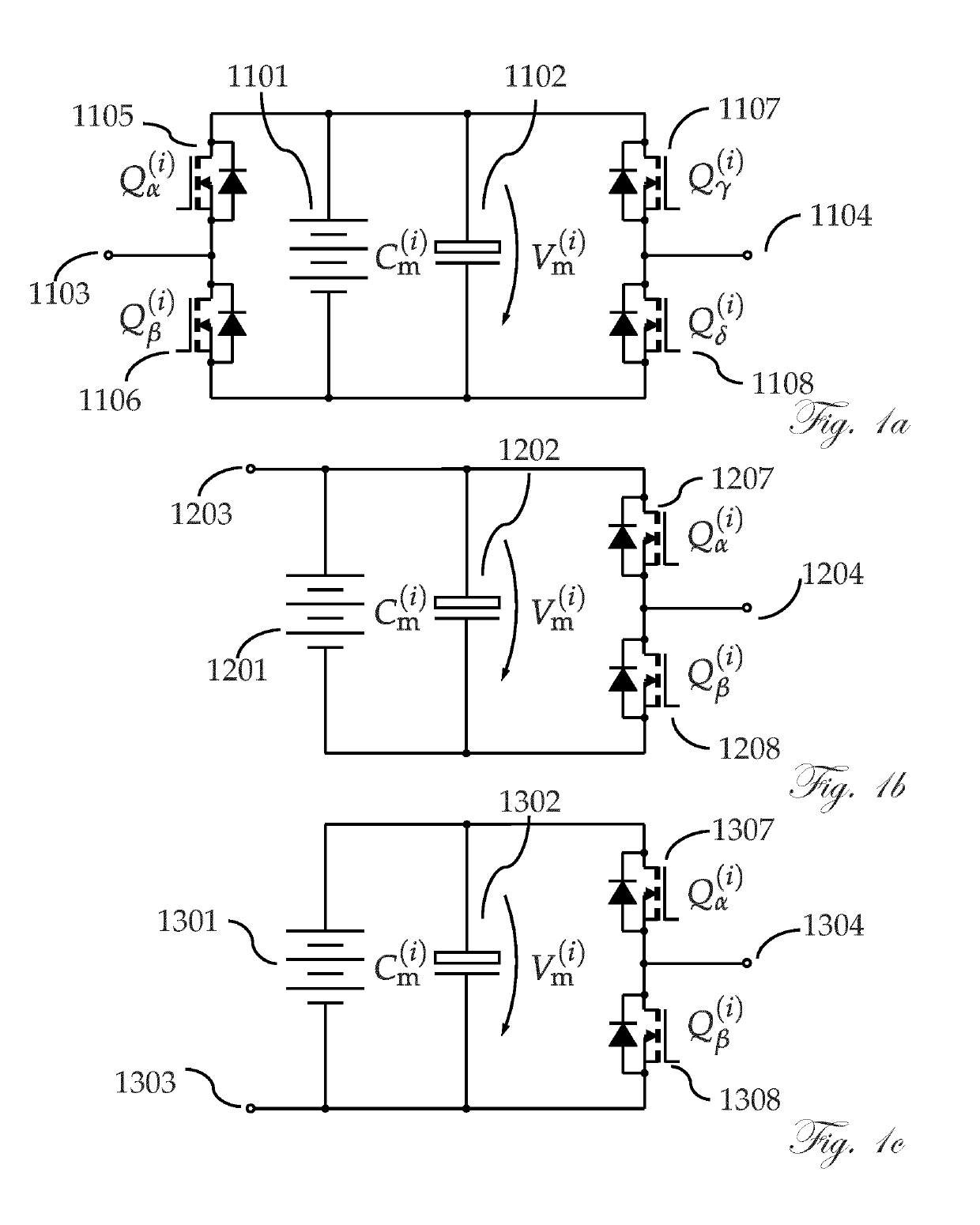
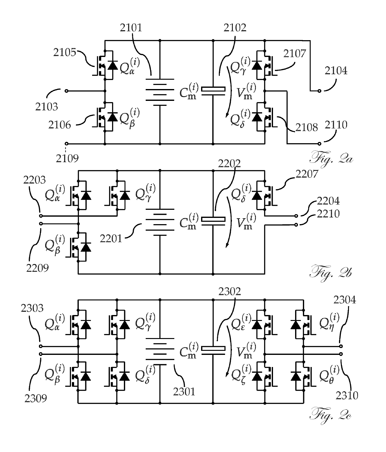
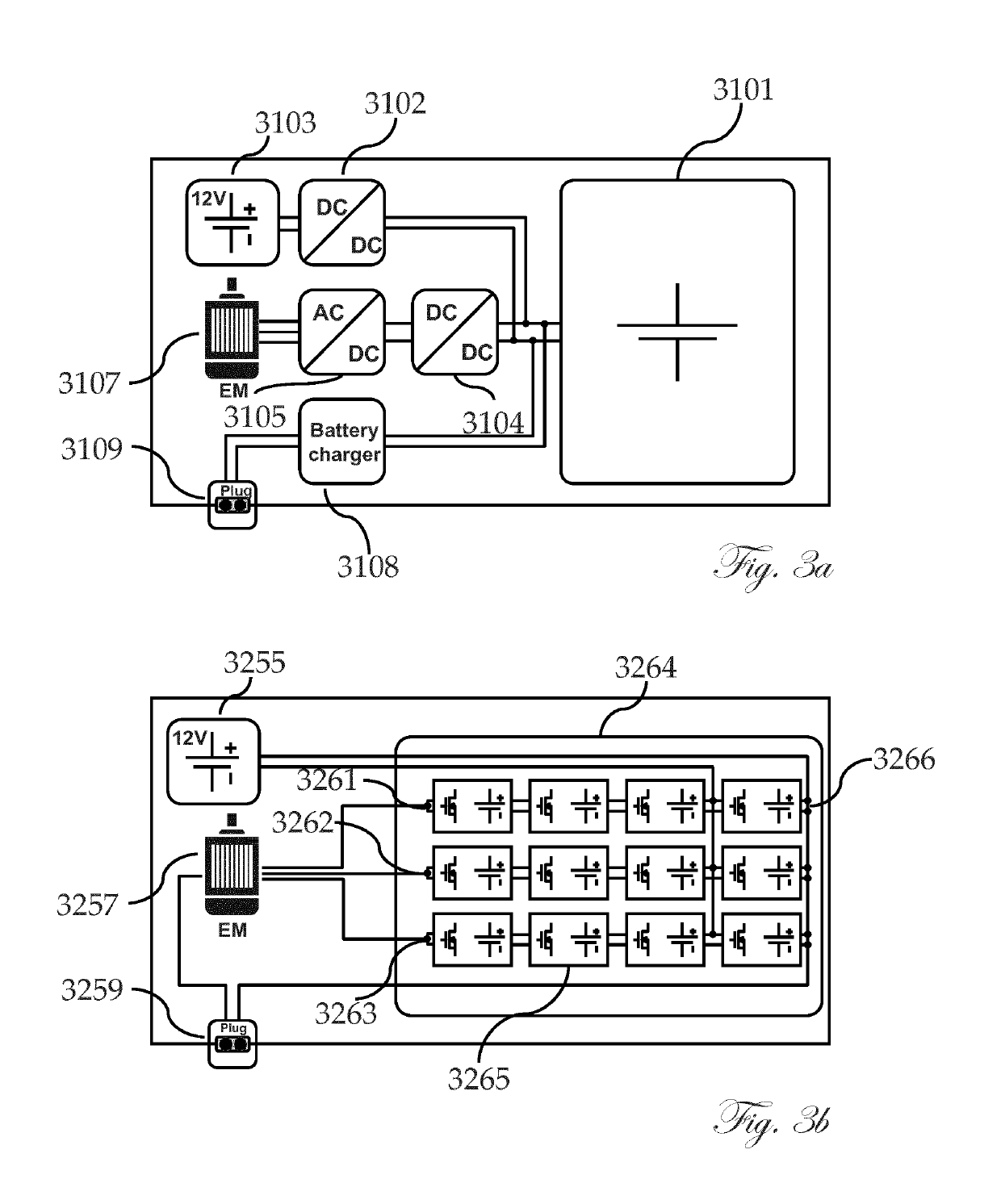
[0037]The invention integrates the traction battery and various power electronic converters for electric vehicles into a single, multi-function unit. Specifically, the invention can integrate the battery, traction boost converter and inverter, drive control, auxiliary power supply bus converter, and high-power charger for both AC and DC power. In addition, further functionalities that are conventionally in separate units can be incorporated into the system and efficiently performed by the same electronics, such as battery management and thermal management. The solution provides unique advantages; these include, among others, higher efficiency, lower cost, and increased reliability.

[0038]A battery and / or a battery subportion according to the present invention refers to all kinds of electrical sources and / or storage elements, including but not limited to galvanic cells, electrochemical primary cells, electrochemical secondary cells, capacitors of various kinds, including double-layer ...


PUM

PropertyMeasurementUnit
energy contentaaaaaaaaaa
rated voltageaaaaaaaaaa
voltagesaaaaaaaaaa

Abstract

A traction power source for electric vehicles in a single unit. Specifically, traction power source integrates several functions, such as the battery and inverter. In addition, further functionalities that are traditionally in separate units can be integrated into the system and efficiently performed by the same electronics, such as battery management and thermal management.

Description

CROSS-REFERENCE TO RELATED APPLICATIONS[0001]This U.S. national phase patent application claims priority to PCT International Patent Application No. PCT / EP2016 / 059453, filed Apr. 27, 2016, which claims priority to British Patent Application No. GB 1507518.7, filed Apr. 30, 2015, the content of each application being incorporated by reference herein in its entirety.FIELD OF THE INVENTION[0002]The present invention relates to a battery-sourced electric power supply, particularly for use in electric drives, e.g., on ships, vehicles, airplanes, and the like.BACKGROUND AND SUMMARY OF THE INVENTION[0003]The invention describes a novel technology that can integrate so far separated power units of a drive system, e.g., of vehicles, ships, and aircraft. The traditional separate units that can be omitted or simplified in consequence include:[0004]one or several DC / DC converters that adjust the battery voltage to one or several electric machines; one or several drive inverters that invert the ...

Claims


Application Information

Patent Timeline
Patent Type & Authority Patents(United States)
IPC IPC(8): H01M10/44B60L50/64B60L50/60B60L58/22H01M10/46H02J7/00H02M7/49H02J7/14
CPCH02J7/0024H02M7/49H02J7/0014H02J7/1423Y02T10/92B60L58/22B60L50/66B60L50/64H02J2310/40Y02T10/70H02J7/0019H02J7/0048H02J7/00308H02J7/00304H02J7/005H02J7/0016H02J7/00309H02M7/4835H02M3/1582H02M3/33573B60L50/50B60L58/19B60L58/10B60L1/00H02J7/00H02J7/0013H02J7/342
Inventor GOETZ, STEFAN
Owner DR ING H C F PORSCHE AG
Why Eureka
Try Eureka