Turbo compressor path and rate control

a compressor path and rate control technology, applied in the direction of electric control, machines/engines, electrochemical generators, etc., can solve problems such as damage and/or instability, and achieve the effect of reducing the response tim

Active Publication Date: 2020-07-30
TOYOTA JIDOSHA KK
View PDF2 Cites 5 Cited by
  • Summary
  • Abstract
  • Description
  • Claims
  • Application Information

AI Technical Summary

Benefits of technology

[0007]The control system may include a back pressure valve. The back pressure valve may be configured to create pressure back to the compressor and fuel cell stack. The electronic control unit may be configured to control one or more positions of the back pressure valve or the bypass valve or the speed of the compressor to adjust the air pressure ratio or the air flow rate. The electronic control unit may be configured to determine a sensitivity. The sensitivity may indicate a change in the pressure ratio relative to a change in the air flow rate at a constant speed, or vice versa. The electronic control unit may determine the path and the rate based on the sensitivity. The electronic control unit may optimize the path and the rate to minimize a response time and control the at least one of the air pressure ratio, the speed or the air flow rate further based on the optimized path and the optimized rate.

Problems solved by technology

When the turbo compressor operates within the surge region or the stall region, the turbo compressor operates outside the normal operation region and damage and / or instability may occur.

Method used


Image

  • Turbo compressor path and rate control
  • Turbo compressor path and rate control
  • Turbo compressor path and rate control

Examples


Embodiment Construction

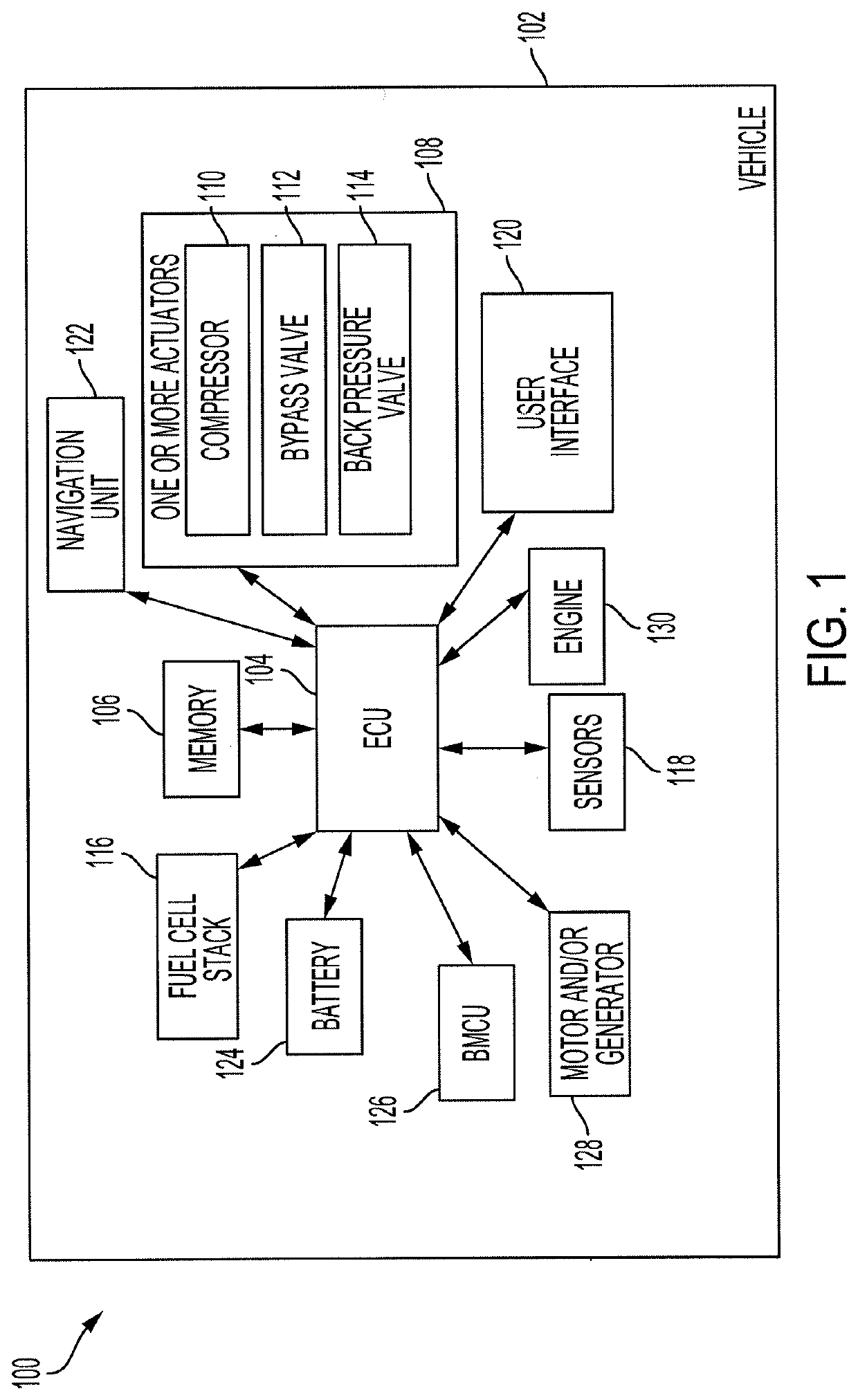
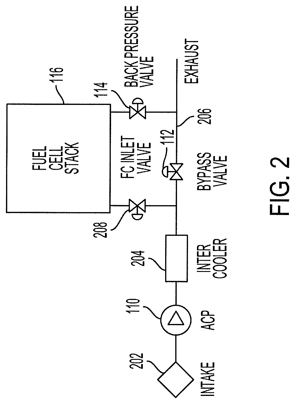
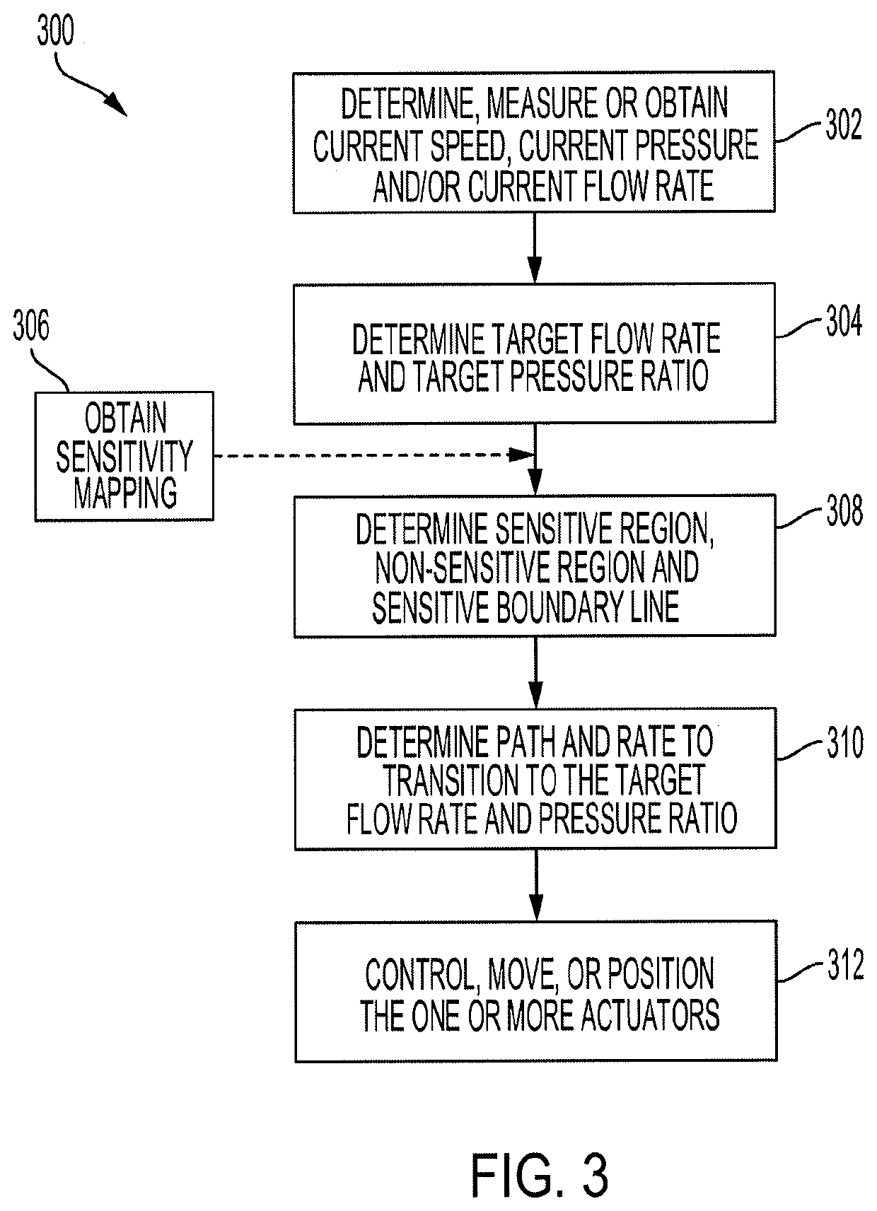
[0019]Disclosed herein are systems, apparatuses and methods for controlling air flow within a vehicle. The control system operates one or more actuators including a compressor (ACP), a bypass valve (APV) or a back pressure valve (AVB) to control the air flow within the vehicle. In electric, hybrids, fuel cell and other vehicles that do not entirely rely on an internal combustion engine, the turbo compressor may need to go from no flow to full flow in a faster amount of time to meet performance targets and other necessary operating conditions, and so, an electrically driven turbo compressor is used. Traditional turbo compressor controls are inadequate to meet the response and operational location requirements necessary. And as such, the control system implements improved rate and path control to meet the response and operational location requirements. This reduces the response time to go from no flow to full flow within the turbo compressor.

[0020]Other benefits and advantages include...


PUM

PropertyMeasurementUnit
response timeaaaaaaaaaa
flow rateaaaaaaaaaa
flow rateaaaaaaaaaa

Abstract

Methods, systems, and devices of a control system. The control system includes a fuel cell stack. The control system includes a compressor that is configured to control and provide a total air flow within the vehicle. The compressor has an air pressure ratio and an air flow rate and operates at a speed. The control system includes an electronic control unit coupled to the fuel cell stack and the compressor. The electronic control unit is configured to determine a path associated with one or more adjustments to the air pressure ratio or the air flow rate. The electronic control unit is configured to determine a rate associated with the one or more adjustments based on the path and control at least one of the air pressure ratio, the speed or the air flow rate to operate the compressor based on the path and the rate.

Description

BACKGROUND1. Field[0001]The present disclosure relates to systems and methods for controlling pressure and flow within a turbo compressor.2. Description of the Related Art[0002]Vehicles, such as electric vehicles (EV), have a fuel cell stack and other components that operate within specific operational parameters, such as pressure and flow rate, so that the vehicle operates at a particular speed. Conventional vehicles, such as a vehicle with an internal combustion engine, have a conventional turbo compressor that operates within certain particular parameters, such as a response time of approximately 1.5 seconds from no flow to full flow. Whereas, EVs have an electric turbo compressor that operates faster with a response time of approximately 0.5 seconds from no flow to full flow.[0003]Moreover, conventional turbo compressors operate within a narrow range inside a normal operation region that is outside a surge region and a stall region. Electric turbo compressors, however, may opera...

Claims


Application Information

Patent Timeline
Patent Type & Authority Applications(United States)
IPC IPC(8): H01M8/04111H01M8/0438H01M8/04746
CPCH01M8/04111H01M8/04395H01M2250/20H01M8/04753F02B39/10F02B39/16F02D41/0007Y02E60/50Y02T90/40
Inventor FARNSWORTH, JARED M.FOLICK, DANIELHASEGAWA, SHIGEKITOMI, NAOKI
Owner TOYOTA JIDOSHA KK
Why Eureka
Try Eureka