System and Method for Routing Chemicals in a Chemical Plant

a chemical plant and system technology, applied in the field of system and a method for routing chemicals, can solve the problems of high operator skill, complicated routing process of chemicals from source to destination, and difficulty in finding the optimum path between source and destination, so as to improve safety and/or reliability, optimize resource utilization, and maximize throughput

Active Publication Date: 2016-08-11
GRANT PRIDECO LP
View PDF5 Cites 6 Cited by
  • Summary
  • Abstract
  • Description
  • Claims
  • Application Information

AI Technical Summary

Benefits of technology

[0051]For improved safety and / or reliability, it may be desirable to install more than one routing control unit and / or more than one routing module. The system may be designed so that the different routing control units and / or routing modules share information through the communications layer. If a routing means fails, another routing means may take over.
[0052]In one embodiment, the routing control unit may be adapted to perform load balancing so as to distribute a workload evenly across two or more computers, network links, CPUs, hard-drives or other resources, in order to optimize resource utilization, maximize throughput, minimize response time and avoid overload. Described below are some of the scenarios which exemplify and illustrate how load balancing may be utilized in the routing control unit:

Problems solved by technology

Because the number of valves, pumps, mixers etc. that need to be engaged typically is large and spread out over a large area, and thus is part of a complex matrix of piping, routing of chemicals from a source to a destination may be a complex and time-consuming process, requiring high skills from an operator.
Finding an optimum path between source and destination is particularly complicated, especially when multiple simultaneous routings / parallel flows are required.
Erroneous or sub-optimal routing of chemicals is therefore quite common, which may result in unwanted situations such as contamination of fluids, the need to discard chemicals, high cost, negative HSE issues, poor drilling efficiency, poor product quality, drilling-downtime, and inferior personnel safety.
With the potential complexity of a chemical plant, the amount of manual involvement in a chemical transfer process makes it highly probable that the transfer process will be sub-optimal or even incorrect, thus leading to potential inefficient transfer, excessive wear of equipment, high equipment down-time, high chemical contamination and excessive waste.

Method used


Image

  • System and Method for Routing Chemicals in a Chemical Plant
  • System and Method for Routing Chemicals in a Chemical Plant
  • System and Method for Routing Chemicals in a Chemical Plant

Examples


Embodiment Construction

[0062]In the following, all figures are shown schematically. The shown features are not necessarily to scale.

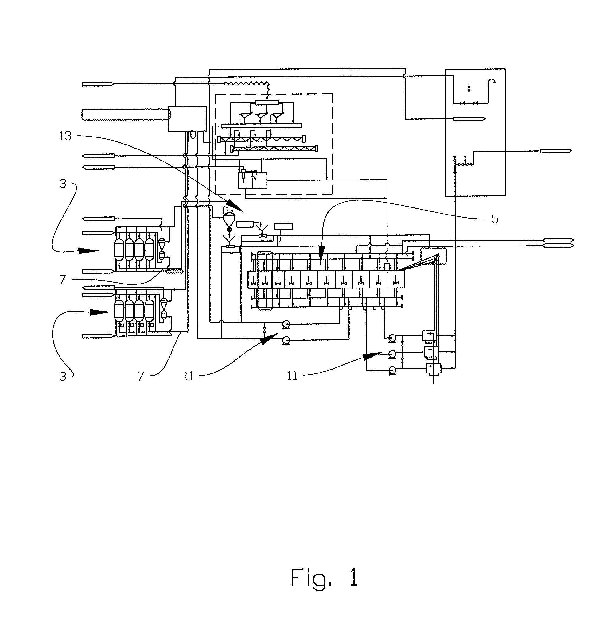
[0063]FIG. 1 shows an overview of a drilling fluid plant 1. The figure is shown as an example of the complexity of a real-life plant for the mixing and treatment of drilling fluids. It is, however, beyond the scope of the present description to describe this plant in detail. Only a few parts of the drilling fluid plant 1 will be described herein. Reference number 3 denotes a plurality of sources in the form of storage pressure tanks for bulk powder barite and cement. A plurality of pipes 7 run from the storage pressure tanks 3 to a plurality of destinations 5 exemplified in the form of mud storage tanks. The bulk powder storage tanks 3 and the mud storage tanks 5 are connected to a mud mixing system 13 via the plurality of pipes 7 and a plurality of valves and pumps 11. The valves are not shown in FIG. 1 for simplicity, but a drilling fluid plant 1 like the one shown in the f...


PUM


Abstract

A system for automatic routing of chemicals includes a plurality of equipment, including a source and a destination, and one or more possible paths between the source and destination. The system further includes a process control unit to communicate with the equipment, a routing control unit to communicate with the process control unit. The routing control unit is provided with control algorithms for finding an optimum path between the source and the destination based at least partially on feedback from the process control unit.

Description

CROSS-REFERENCE TO RELATED APPLICATIONS[0001]The present application is a 35 U.S.C. §371 national phase application of PCT / NO2014 / 050174 with international filing date of Sep. 23, 2014 and claims priority thereto, and further claims priority to provisional applications U.S. 61 / 881,648 and U.S. 61 / 991,076. Each of the three above-identified applications is incorporated herein by reference in its entirety for all purposesSTATEMENT REGARDING FEDERALLY SPONSORED RESEARCH OR DEVELOPMENT[0002]Not applicable.BACKGROUND[0003]The present disclosure relates to a system and a method for routing of chemicals, such as chemicals related to drilling fluids. In the following discussion, drilling fluids and a drilling fluid plant will be used to exemplify the disclosure, though the invention, claimed below, is not limited to this specific use.[0004]Drilling Fluids are made up of many different chemicals (additives); some in powder form and others in liquid form. The composition of the chemicals vari...

Claims


Application Information

Patent Timeline
Patent Type & Authority Applications(United States)
IPC IPC(8): G05D7/06G05B13/04
CPCE21B21/062G05D7/0635G05B13/041E21B2041/0028E21B2200/22G05B2219/31382E21B44/00G05B19/02B01F35/00
Inventor KRISTOFFERSEN, SVENNSØRENSEN, JAN HELGEHERTZENBERG, TORMODKLEMETSEN, THOMASARORA, DEEPAK
Owner GRANT PRIDECO LP
Why Eureka
Try Eureka