
Composition for forming resist underlayer film with reduced outgassing

a technology of resist and underlayer film, applied in the field of compositions for forming resist underlayer films, to achieve the effect of preventing volatilization of molecules, suppressing outgassing, and suppressing the amount of outgassing

Active Publication Date: 2019-10-08
NISSAN CHEM IND LTD
View PDF40 Cites 0 Cited by
  • Summary
  • Abstract
  • Description
  • Claims
  • Application Information

AI Technical Summary

Benefits of technology

The underlayer film effectively reduces outgassing to 1.00×10^14 molecules / cm² / s, enhances adhesion and etching speed, and prevents contamination, addressing reflection and static electrification issues during high-energy radiation exposure.

Problems solved by technology

The exposure using such high-energy rays has a problem of contamination in a chamber by the outgassing due to the decomposition of a coated material.

Method used


Image

  • Composition for forming resist underlayer film with reduced outgassing
  • Composition for forming resist underlayer film with reduced outgassing
  • Composition for forming resist underlayer film with reduced outgassing

Examples


synthesis example 1

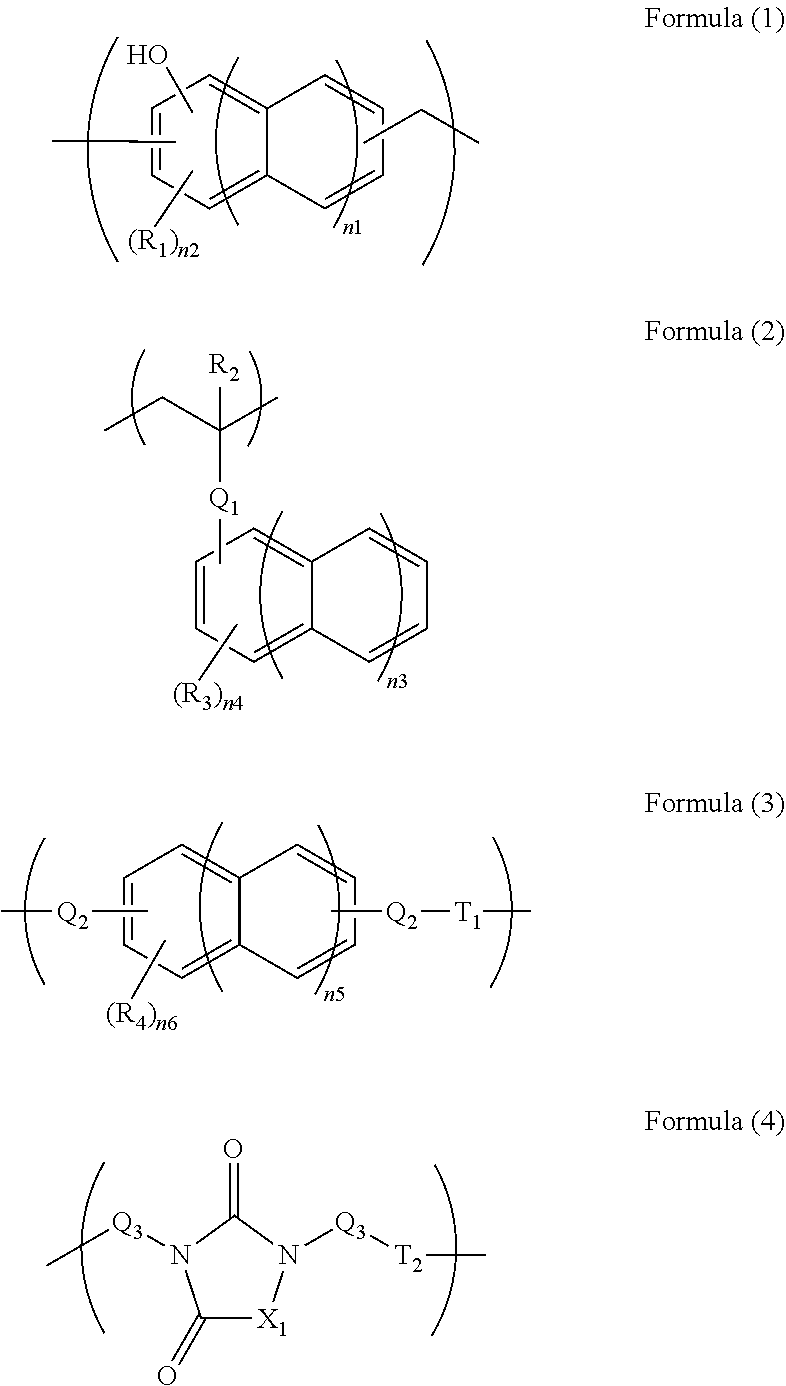
[0082]In 34.10 g of propylene glycol monomethyl ether, 5.00 g of monoallyldiglycidylisocyanuric acid (manufactured by Shikoku Chemicals Corporation), 3.32 g of 5-hydroxyisophthalic acid, and 0.21 g of benzyltriethylammonium chloride were dissolved, and then the whole was reacted at 130° C. for 4 hours to give a polymer compound solution. The obtained polymer compound corresponded to Formula (4-2) and had a weight average molecular weight of 17,000 in terms of standard polystyrene. The obtained polymer contained a triazinetrione ring and a benzene ring at a total content of 69% by mass in terms of cyanuric acid and in terms of benzene ring, respectively.

synthesis example 2

[0083]In 204.50 g of propylene glycol monomethyl ether, 11.00 g of tris(2,3-epoxypropyl)isocyanuric acid (Nissan Chemical Industries, Ltd., trade name TEPIC), 39.50 g of 3,5-diiodosalicylic acid, and 0.63 g of benzyltriethylammonium chloride were dissolved, and then the whole was reacted at 130° C. for 4 hours to give a polymer compound solution. The obtained polymer compound corresponded to Formula (4-4) and had a weight average molecular weight of 1,200 in terms of standard polystyrene. The obtained polymer contained a triazinetrione ring and a benzene ring at a total content of 27% by mass in terms of cyanuric acid and in terms of benzene ring, respectively.

synthesis example 3

[0084]A solution of 16.00 g of 2-vinylnaphthalene, 2.00 g of glycidyl methacrylate, and 2.00 g of 1-butoxyethyl methacrylate dissolved in 60.8 g of cyclohexanone was heated to 80° C. To the solution, a solution of 0.20 g of azobisisobutyronitrile dissolved in 20 g of cyclohexanone was slowly added. After the completion of the addition, the whole was reacted for 24 hours at 80° C. to give a polymer compound solution. The obtained polymer compound corresponded to Formula (2-1) and had a weight average molecular weight of 6,000 in terms of standard polystyrene. The obtained polymer contained a naphthalene ring at a content of 79% by mass in terms of naphthalene.


PUM

PropertyMeasurementUnit
thicknessaaaaaaaaaa
temperatureaaaaaaaaaa

Abstract

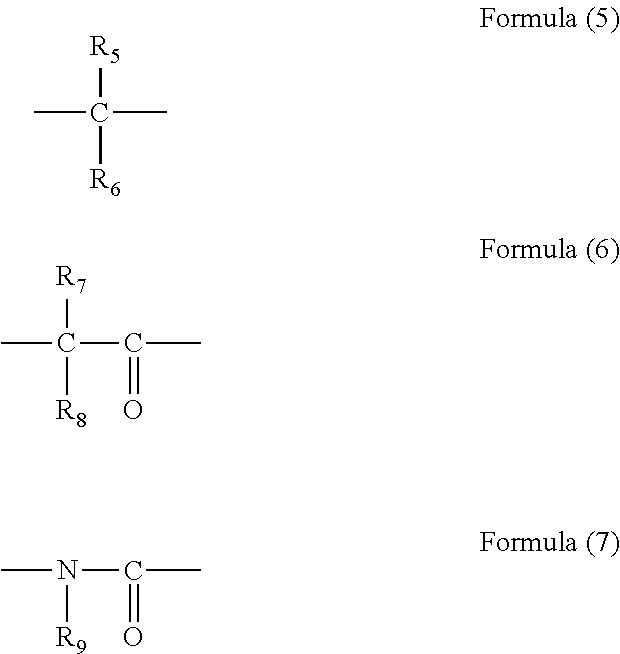
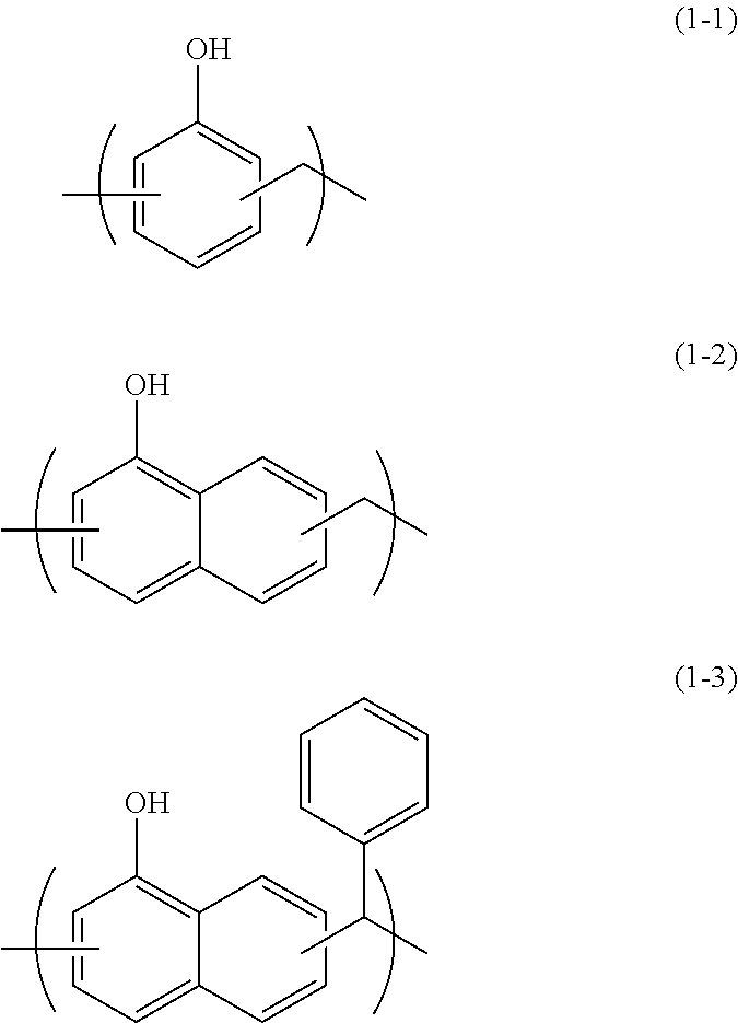
Underlayer films of high-energy radiation resists applied onto semiconductor substrates in a lithography process for producing semiconductor devices and that are used to prevent reflection, static electrification, and development defects and to suppress outgassing during the exposure of resist layers with high-energy radiation are prepared from compositions including a film component having an aromatic ring structure or a hetero ring structure. The film component having an aromatic ring structure or a hetero ring structure is contained at a proportion of 5 to 85% by mass. The film component may be a compound having an aromatic ring structure or a hetero ring structure, and the compound may be a polymer or a polymer precursor including a specific repeating unit. The aromatic ring may be a benzene ring or fused benzene ring, and the hetero ring structure may be triazinetrione ring.

Description

TECHNICAL FIELD[0001]The present invention relates to compositions for forming resist underlayer films. In particular, the present invention relates to underlayer films of high-energy radiation resists that are applied onto semiconductor substrates in a lithography process for producing semiconductor devices and that are used to prevent reflection, static electrification, and development defects and to suppress outgassing during the exposure of resist layers with high-energy radiation.BACKGROUND ART[0002]Conventionally, microfabrication has been carried out by lithography using photoresist compositions in the production of semiconductor devices. The microfabrication is a machining process in which a thin film of a photoresist composition is formed on a silicon wafer, active rays such as ultraviolet rays are radiated onto the film through a mask with a pattern of a semiconductor device followed by development, and the silicon wafer is etched using the obtained resist pattern as a pro...

Claims


Application Information

Patent Timeline
Patent Type & Authority Patents(United States)
IPC IPC(8): G03F7/09
CPCG03F7/093G03F7/091
Inventor SAKAMOTO, RIKIMARUHO, BANGCHINGENDO, TAKAFUMI
Owner NISSAN CHEM IND LTD
Learn More