
Perovskite catalysts enhanced combustion on porous media

a technology of perovskite catalysts and porous media, which is applied in the direction of combustion using catalytic materials, physical/chemical process catalysts, combustion types, etc., can solve the problems of high catalytic activity of noble metals, ceramic catalytic properties will degrade, and the fuel burned more efficiently and efficiently

Inactive Publication Date: 2019-09-03
UNIV OF CENT FLORIDA RES FOUND INC
View PDF6 Cites 0 Cited by
  • Summary
  • Abstract
  • Description
  • Claims
  • Application Information

AI Technical Summary

Benefits of technology

This patent describes a new technology for burning fuels in a catalyst-coated porous media. This technology can achieve high temperatures to support heat and power applications while keeping the materials in the combustion chamber active and preventing degradation at high temperatures. This allows for more efficient fuel-burning and the use of lean mixtures, which reduces harmful emissions and allows for flexibility in fuel flexibility. The technology is simple, efficient, and can be used in various applications such as internal combustion engines, water heaters, gas stoves, boilers, and portable generators. Overall, this technology improves temperature conditions for more efficient fuel-burning and allows for better environmental contamination control and energy resource utilization.

Problems solved by technology

However, SiC coated porous media did not outperform the inert Al2O3 matrix when the lean mixtures were used.
Thus, SiC helps to promote the complete combustion reactions, however, it is possibly prone to the oxidation itself during combustion and, once the significant amounts of SiO2 phase forms on the surface of SiC, the catalytic properties of the ceramic will degrade.
However, while catalytic activity of noble metals is high, their cost is also very high, and their possible sublimation and / or sintering can occur in a catalytic burner at high temperatures in the presence of water and CO2 gasses.
Another problem in the catalytic combustion of methane and other hydrocarbons is carbon deposition and, as a result, catalyst deactivation.
Conventional engines have relied on complex control equipment and large devices whose configurations created undesirably large pressure drops across the combustion chambers, compromising ideal combustion efficiency while requiring intricate control systems, making them impractical for use outside of academia.
For example, some or all of the discussed patents / publications / experiments / work may not be sufficiently early in time, may not reflect subject matter developed early enough in time and / or may not be sufficiently enabling so as to amount to prior art for patent law purposes.

Method used


Image

  • Perovskite catalysts enhanced combustion on porous media
  • Perovskite catalysts enhanced combustion on porous media
  • Perovskite catalysts enhanced combustion on porous media

Examples


example 1

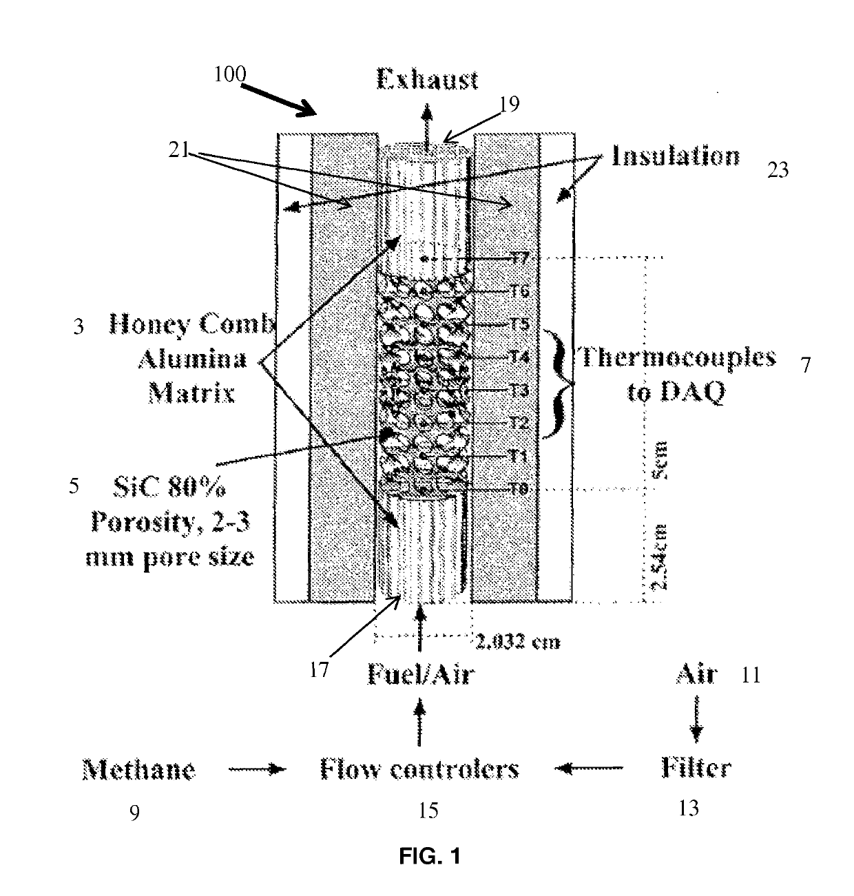
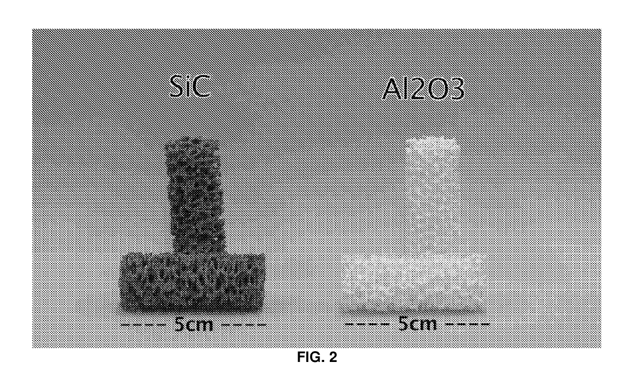
[0045]This Example describes the experimental setup used in the study. Referring to FIG. 1, in one embodiment, a schematic representation of a matrix stabilized porous burner with a combustion chamber 100 is provided. More particularly, the combustion chamber 100 can be composed of two types of porous media: two alumina honeycombs 3 at each end of the combustion chamber, and a reticulated SiC or alumina foam 5 in the middle. Eight K-Type thermocouples (T0-T7; collectively “7”) were placed along the axis of the cylindrical SiC foam, equidistantly spaced, 0.72 cm apart, as seen in FIG. 1. These eight thermocouples measured the temperature distribution within the combustion chamber. They have an uncertainty of 0.75% from 0 to 1250° C. The thermocouples were connected to a National Instruments data acquisition system (NI USB-6210), and then logged into LabView virtual instrument for data collection.

[0046]High grade methane 9 (99% purity) and dry laboratory compressed air 11 were used in...

example 2

[0049]This Example describes the preparation of the multiple samples of reticulated foam ceramics use in the study. In addition to the uncoated inert reticulated foam, perovskite catalyst coated reticulated foams were used. By conducting several runs of both inert and catalytically enhanced reticulated foams, the run to run variation and repeatability could be measured.

[0050]The catalytically enhanced ceramics were coated using the dip coating method. In brief, eight samples of SiC articulated foams were coated with five different compositions of perovskite catalysts (as referenced above). The dip coating process consisted of dissolving the perovskite powders in isopropyl alcohol and placing the slurry mixture in a test tube submerged in a water bath within an ultrasound machine to ensure homogenization of the slurry. The reticulated foam ceramic was then lowered into the slurry and held suspended for one minute, which allowed enough time for the coating to penetrate the pores and b...

example 3

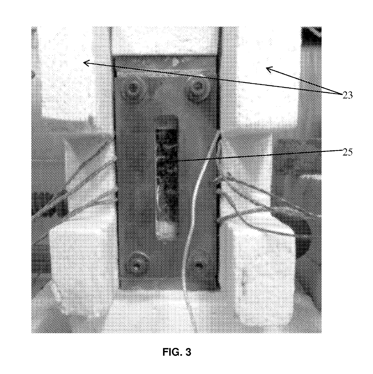
[0051]This Example describes the initial ignition and use of the burner in the study, in addition to certain related results. The reactants enter the burner from the bottom portion 17 of the combustion chamber 100 as seen in FIG. 1. The burner is first ignited, near the top of the reticulated foam ceramic or at the thermocouple location T7, at Φ=1.0. Once ignited the Φ is reduced to 0.7. The fuel flow rate was varied to obtain the desired Φ, the air volumetric flow rate is held constant at 0.008 m3 / min throughout the experiment. After ignition, at Φ=0.7, the premixed combustion wave will propagate in the opposite direction of the flow. Through the quartz window (FIG. 3, ref. No. 25), the combustion zone was observed as a highly luminescent zone slowly traveling upstream. The combustion wave is allowed to travel against the direction of the flow to record the eventual downstream movement of the wave once the Φ is further reduced. This initial value of Φ=0.7 is used to warm up the com...


PUM

PropertyMeasurementUnit
porosityaaaaaaaaaa
pore sizeaaaaaaaaaa
pore sizeaaaaaaaaaa

Abstract

The effects of different perovskite catalysts, catalytic active materials with a crystal structure of ABO3, on matrix stabilized combustion in a porous ceramic media are explored. Highly porous silicon carbide ceramics are used as a porous media for a catalytically enhanced matrix stabilized combustion of a lean mixture of methane and air. A stainless steel combustion chamber was designed incorporating a window for direct observation of the flame within the porous media. Perovskite catalytic enhancement of SiC porous matrix with La0.75Sr0.25Fe0.6Cr0.35Ru0.05O3; La0.75Sr0.25Fe0.6Cr0.4O3; La0.75Sr0.25Fe0.95Ru0.05O3; La0.75Sr0.25Cr0.95Ru0.05O3; and LaFe0.95Ru0.05O3, for example, were used to enhance combustion. The flammability limits of the combustion of methane and air were explored using both inert and catalytically enhanced surfaces of the porous ceramic media. By coating the SiC porous media with perovskite catalysts it was possible to lower the minimum stable equivalence ratio.

Description

RELATED APPLICATION DATA[0001]The present application claims priority to and the benefit of U.S. provisional patent application No. 61 / 954,060, filed on Mar. 17, 2014, the entire contents of which are hereby incorporated by reference.FIELD OF THE INVENTION[0002]The present disclosure is directed generally to combustion apparatuses, and more particularly, to superadiabatic combustion utilizing a perovskite composition catalytically enhanced porous matrix, in matrix stabilized porous burner technology.BACKGROUND[0003]Matrix stabilized porous burner technology is an advanced combustion method in which a mixture of fuel and oxidizer is burned within a solid porous medium, as opposed to open, burner-stabilized flames such as that on a Bunsen burner. The advantages of porous burners over that of burner-stabilized flames is mainly due to the thermal feedback effect provided by the solid medium through which heat conduction in the upstream direction results in preheating the incoming reacta...

Claims


Application Information

Patent Timeline
Patent Type & Authority Patents(United States)
IPC IPC(8): F23C13/08B01J23/86B01J23/89B01J27/224B01J23/00B01J23/652
CPCF23C13/08B01J27/224B01J23/002B01J23/6522B01J23/862B01J23/8906B01J23/894B01J23/8946B01J23/8993B01J2523/00B01J2523/24B01J2523/3706B01J2523/67B01J2523/821B01J2523/842
Inventor ORLOVSKAYA, NINACHEN, RUEY-HUNGROBAYO, MANUEL
Owner UNIV OF CENT FLORIDA RES FOUND INC
Learn More