Method to Enhance Burner Efficiency and Burner
a burner efficiency and burner technology, applied in the direction of combustion types, furnaces, lighting and heating apparatuses, etc., can solve the problems of difficult design and execution of injection gaps of individual primary air flows of burners in operation, difficult to design and execute injection gaps of individual primary air flows of burners, and employed mechanisms that cannot withstand extreme conditions inside the clinker kiln
Inactive Publication Date: 2019-04-18
DYNAMIS ENGENHARIA E COMERCIO
View PDF10 Cites 2 Cited by
- Summary
- Abstract
- Description
- Claims
- Application Information
AI Technical Summary
Problems solved by technology
Hence, whereas the features related to primary air mass flow and injection velocities of each individual primary air portion are operational parameters, the geometry changing of nozzles and/or injection gaps of the individual primary air flows of a burner in operation is very difficult to design and execute, in view of the high temperatures and materials used.
In the very few cases, wherein the burner presents this factory option, dur
Method used
View moreImage
Smart ImageViewing Examples
Examples
 PUM
 Abstract
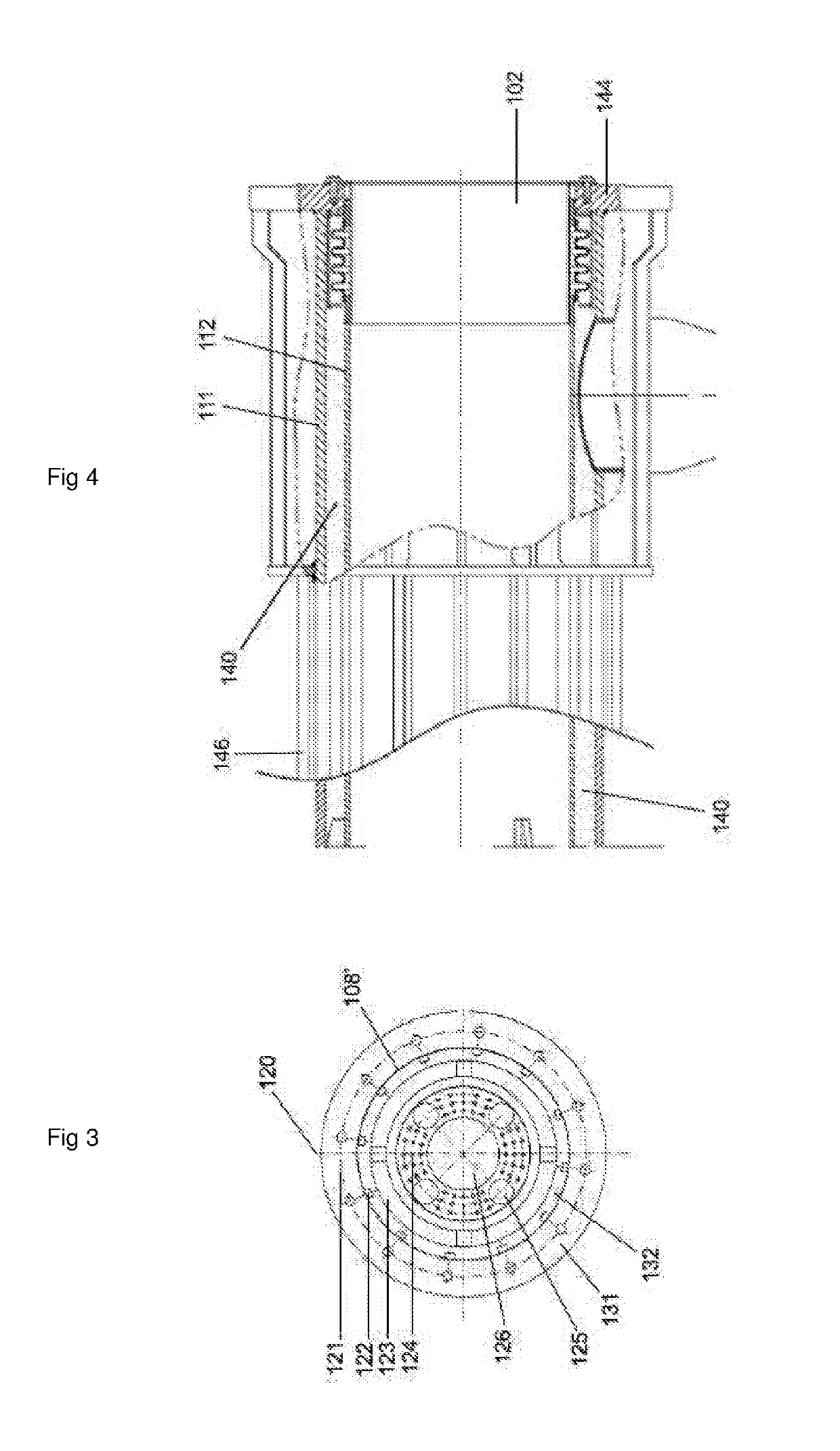
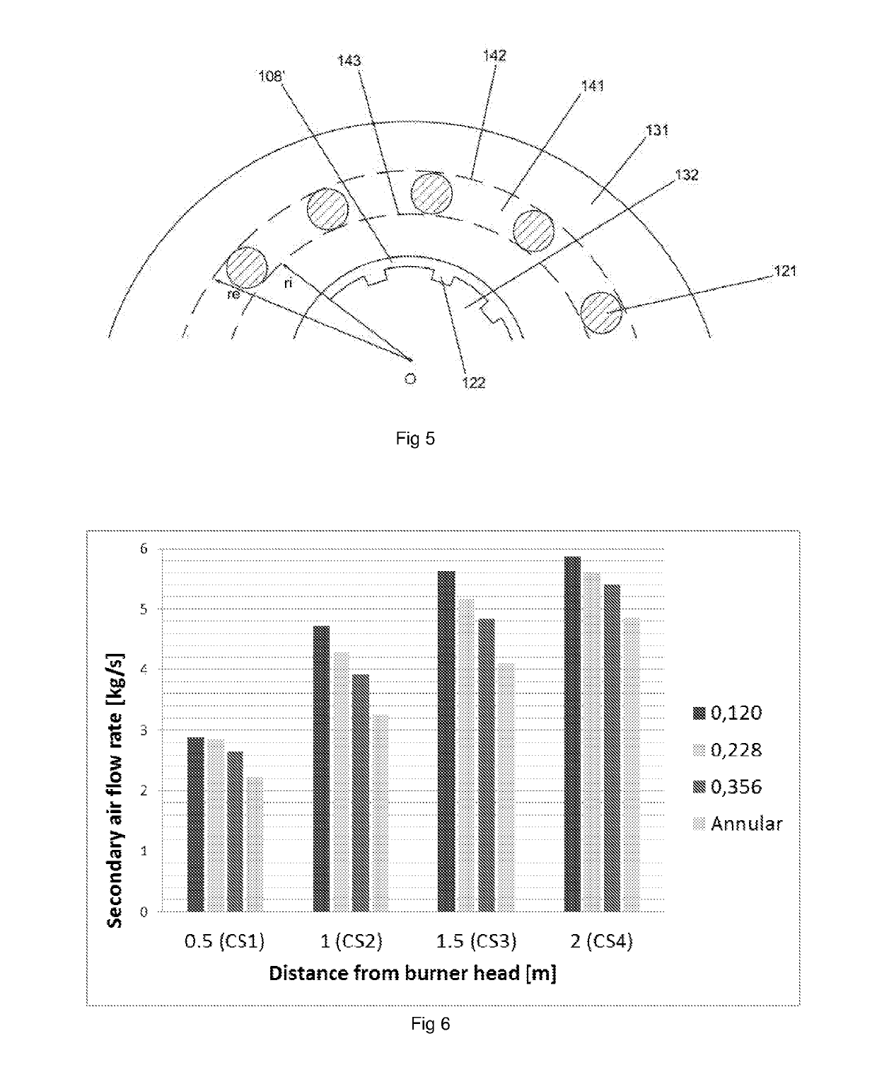
A burner barrel includes a concentric multi-tubular structure, formed by pipes and at the end downstream the burner barrel is provided a burner tip in which various nozzles to inject fuel and primary air are perforated. The burner tip includes at least one series of nozzles intended to inject an external air flow; a second series of nozzles intended to inject tangential air flow; and a third series of apertures intended to inject the fuel and transport air. The ends downstream of the first and second burner pipes are joined and define a continuous external annular surface of the burner tip. The nozzles are arranged within an inscribed area, being the dimension of the nozzles limited by a rate between the open area A of the nozzles and the complementary closed area A.
Description
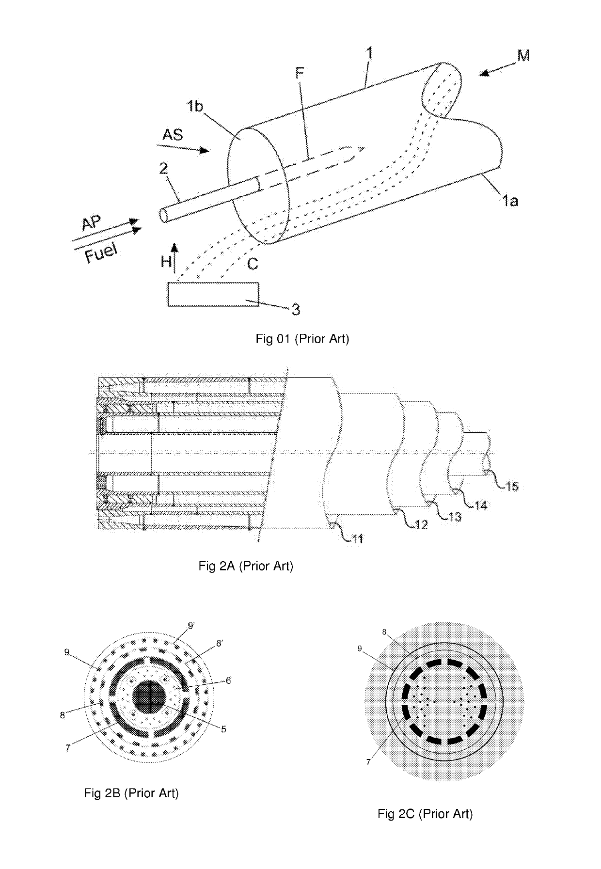
[0001]The present invention relates to improved burners to be used in cement production kilns.STATE OF ART[0002]As it is well known, the cement production consists, briefly, from the steps of raw material extraction; grinding, mixing and homogenization; clinkerization in rotary kilns; clinker cooling; grinding and bagging the produced cement.[0003]Among these steps, the most critical is the mentioned clinkerization of the previously homogenized mixture, which is carried out in large, cylindrically shaped rotary kilns, provided with controlled burners in order to establish a suitable temperature in each rotary kiln's region. Considering this focus, two fundamental aspects regarding the mentioned burners stand out: the energy efficiency and the promptness in the thermal responses.[0004]An example of a rotary kiln is illustrated, schematically, in FIG. 1. In said figure, a rotary kiln is indicated with the number (1) and it is intended to burn said pre-homogenized mixture (M) in counte...
Claims
Login to View More Application Information
Patent Timeline
 IPC IPC(8): F23D1/00F23D1/04F27B7/10
CPCF23D1/005F23D1/04F27B7/10F23D1/00F23C6/045F23C7/002F23C2201/20F23C2900/06041F23C2900/06043
Inventor MARTINS FERREIRA, GUILHERMEVON RAINER FABIANI, LUIS FILIPEDE PINHO, LUIZ FELIPEDE SOUSA BORGES, RODRIGO
Owner DYNAMIS ENGENHARIA E COMERCIO
Features
- R&D
- Intellectual Property
- Life Sciences
- Materials
- Tech Scout
- Unparalleled Data Quality
- Higher Quality Content
- 60% Fewer Hallucinations
Learn More Browse by: Latest US Patents, China's latest patents, Technical Efficacy Thesaurus, Application Domain, Technology Topic, Popular Technical Reports.
© 2025 PatSnap. All rights reserved.Legal|Privacy policy|Modern Slavery Act Transparency Statement|Sitemap|About US| Contact US: help@patsnap.com


