
Methods and apparatus for predicting performance of a measurement method, measurement method and apparatus

a measurement method and measurement method technology, applied in the direction of instruments, material analysis, printing, etc., can solve the problems of commercial unattractive implementation of small-target dark-field imaging, the inability of modern lithographic technology to measure directly the smallest features of modern lithographic processes, and the inability to measure the smallest features directly. to achieve the effect of improving the throughput of inspection apparatus

Active Publication Date: 2019-08-13
ASML NETHERLANDS BV
View PDF24 Cites 0 Cited by
  • Summary
  • Abstract
  • Description
  • Claims
  • Application Information

AI Technical Summary

Benefits of technology

This approach enhances the throughput of inspection processes by allowing simultaneous measurement of multiple targets without the need for dark-field imaging, improving the accuracy and efficiency of overlay and asymmetry measurements in lithographic processes.

Problems solved by technology

This limits the smallest features that can be measured, so that the technique can no longer measure directly the smallest features made in modern lithographic processes.
Unfortunately, the cost and other limitations of optical systems compatible with such wavelengths make it commercially unattractive to implement small-target dark-field imaging.

Method used


Image

  • Methods and apparatus for predicting performance of a measurement method, measurement method and apparatus
  • Methods and apparatus for predicting performance of a measurement method, measurement method and apparatus
  • Methods and apparatus for predicting performance of a measurement method, measurement method and apparatus

Examples


Embodiment Construction

[0036]Before describing embodiments of the invention in detail, it is instructive to present an example environment in which embodiments of the present invention may be implemented.

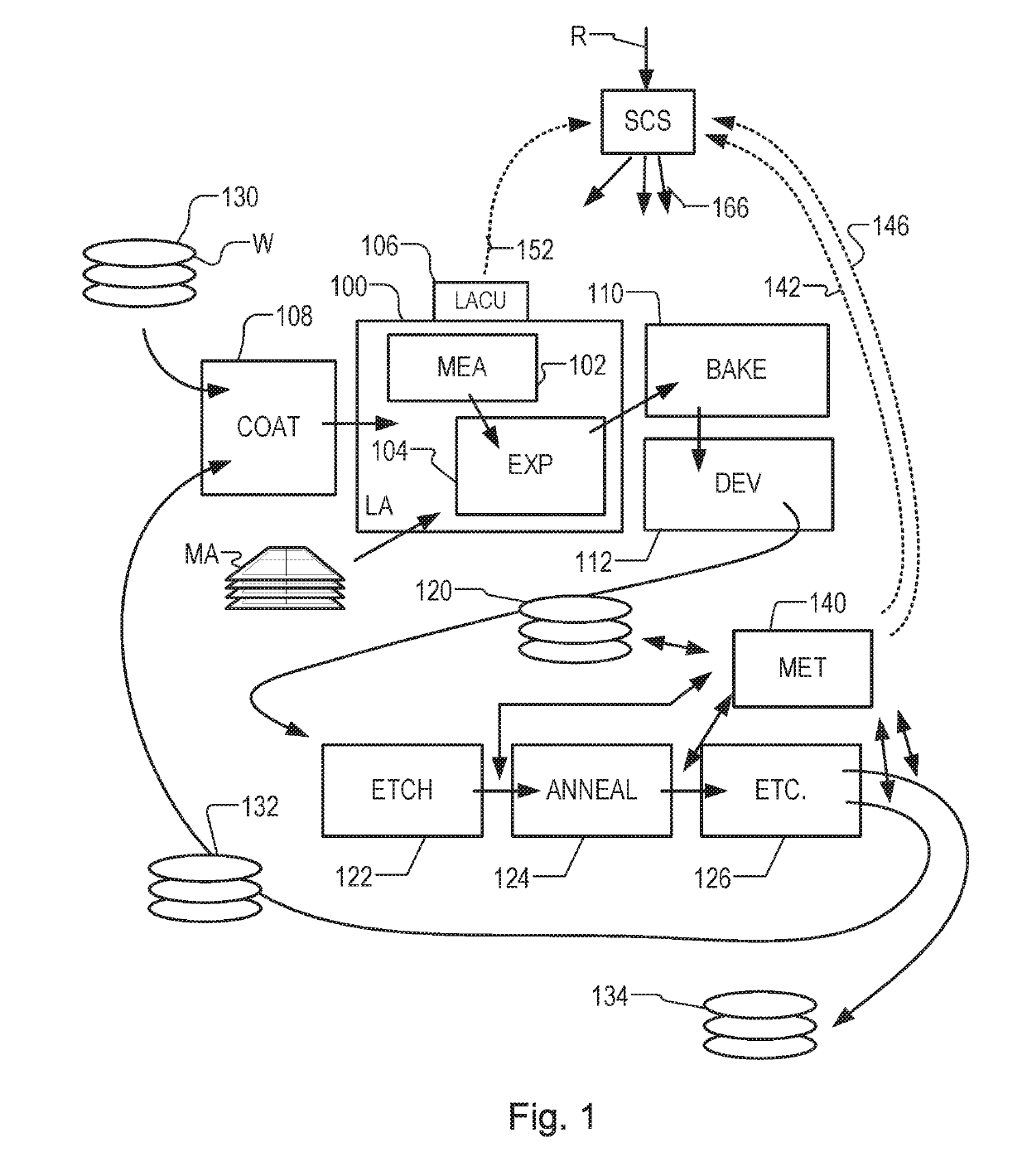
[0037]FIG. 1 at 100 shows a lithographic apparatus LA as part of an industrial facility implementing a high-volume, lithographic manufacturing process. In the present example, the manufacturing process is adapted for the manufacture of for semiconductor products (integrated circuits) on substrates such as semiconductor wafers. The skilled person will appreciate that a wide variety of products can be manufactured by processing different types of substrates in variants of this process. The production of semiconductor products is used purely as an example which has great commercial significance today.

[0038]Within the lithographic apparatus (or “litho tool”100 for short), a measurement station MEA is shown at 102 and an exposure station EXP is shown at 104. A control unit LACU is shown at 106. In this example...


PUM

PropertyMeasurementUnit
wavelengthsaaaaaaaaaa
soft x-ray wavelengthsaaaaaaaaaa
wavelengthsaaaaaaaaaa

Abstract

Target structures such as overlay gratings (Ta and Tb) are formed on a substrate (W) by a lithographic process. The first target is illuminated with a spot of first radiation (456a, Sa) and simultaneously the second target is illuminated with a spot of second radiation (456b, Sb). A sensor (418) detects at different locations, portions (460x−, 460x+) of said first radiation that have been diffracted in a first direction by features of the first target and portions (460y−, 460y+) of said second radiation that have been diffracted in a second direction by features of the second target. Asymmetry in X and Y directions can be detected simultaneously, reducing the time required for overlay measurements in X and Y. The two spots of radiation at soft x-ray wavelength can be generated simply by exciting two locations (710a, 710b) in a higher harmonic generation (HHG) radiation source or inverse Compton scattering source.

Description

FIELD[0001]The present disclosure relates to methods and apparatus for inspection (e.g., metrology) usable, for example, in the manufacture of devices by lithographic techniques and to methods of manufacturing devices using lithographic techniques.BACKGROUND[0002]A lithographic apparatus is a machine that applies a desired pattern onto a substrate, usually onto a target portion of the substrate. A lithographic apparatus can be used, for example, in the manufacture of integrated circuits (ICs). In that instance, a patterning device, which is alternatively referred to as a mask or a reticle, may be used to generate a circuit pattern to be formed on an individual layer of the IC. This pattern can be transferred onto a target portion (e.g., including part of, one, or several dies) on a substrate (e.g., a silicon wafer). Transfer of the pattern is typically via imaging onto a layer of radiation-sensitive material (resist) provided on the substrate. In general, a single substrate will con...

Claims


Application Information

Patent Timeline
Patent Type & Authority Patents(United States)
IPC IPC(8): G03B27/42G03F7/20G01B11/27G01N21/47G01N21/956G03F9/00
CPCG03F7/70633G01B11/272G01N21/4788G01N21/956G03F9/7088G03F7/70525G03F7/70625G03F9/7069G03F7/7085G03F7/706847
Inventor MATHIJSSEN, SIMON GIJSBERT JOSEPHUSROOBOL, SANDER BASLIN, NANCOENE, WILLEM MARIE JULIA MARCELDEN BOEF, ARIE JEFFREY
Owner ASML NETHERLANDS BV
Learn More