Thin-plate LN optical control device

a technology of optical control device and thin plate, which is applied in the direction of optical waveguide light guide, optical light guide, instruments, etc., can solve the problems of disconnection or short circuit due to migration, ln substrate that is thinned to several tens of m or less, and may be broken, etc., to achieve satisfactory reproducibility, excellent mass productivity, and suppress the effect of dc drift amoun

Active Publication Date: 2019-07-23
SUMITOMO OSAKA CEMENT CO LTD
View PDF4 Cites 3 Cited by
  • Summary
  • Abstract
  • Description
  • Claims
  • Application Information

AI Technical Summary

Benefits of technology

[0013]An object of the invention is to solve a problem related to an increase in a DC drift amount, a great variation between samples, and low reproducibility which occur in a thin-plate LN optical control device in which a thin-plate LN optical waveguide element is accommodated in a housing, in which an atmosphere inside thereof is substituted with an inert gas that does not contain moisture, by using an air-tight sealing structure. In addition, another object of the invention is to provide a thin-plate LN optical control device in which drive voltage is low, an optical bandwidth is broad, reliability is high, and mass productivity is excellent.
[0019]According to the aspect of the invention, in the thin-plate LN optical control device including: the thin-plate LN optical waveguide element which includes the optical waveguide formed by thermal diffusion of Ti in the LN substrate, and the control electrode that is formed on the substrate and is configured to control a light wave propagating through the optical waveguide, and in which at least a part of the substrate is thinned; and the housing that accommodates the thin-plate LN optical waveguide element in an air-tight sealing manner, since oxygen is contained in the filler gas inside the housing, it is possible to suppress an increase in DC drift amount. In addition, a variation between samples is small, and thus satisfactory reproducibility is obtained. As a result, it is possible to obtain a thin-plate LN optical control device excellent in mass productivity.

Problems solved by technology

When being left as is in a moisture-containing atmosphere, an adhesive force of an organic material such as the adhesive may deteriorate.
In addition, in a case where application of a voltage is performed continuously in the moisture-containing atmosphere, disconnection or short-circuiting due to migration may occur in the electrical interconnection.
However, there is a concern that an LN substrate that is thinned to several tens of μm or less may be broken, and thus the LN substrate is fixed to a reinforcing substrate by using an adhesive.
Accordingly, it is not easy to perform the above-described chemical and thermal treatments.
In addition, mass productivity is low under mechanical processing conditions in which the processing damage does not occur, and thus an inspection process is necessary.

Method used


Image

  • Thin-plate LN optical control device
  • Thin-plate LN optical control device
  • Thin-plate LN optical control device

Examples


Embodiment Construction

[0031]Hereinafter, a thin-plate LN optical control device of the invention will be described in detail.

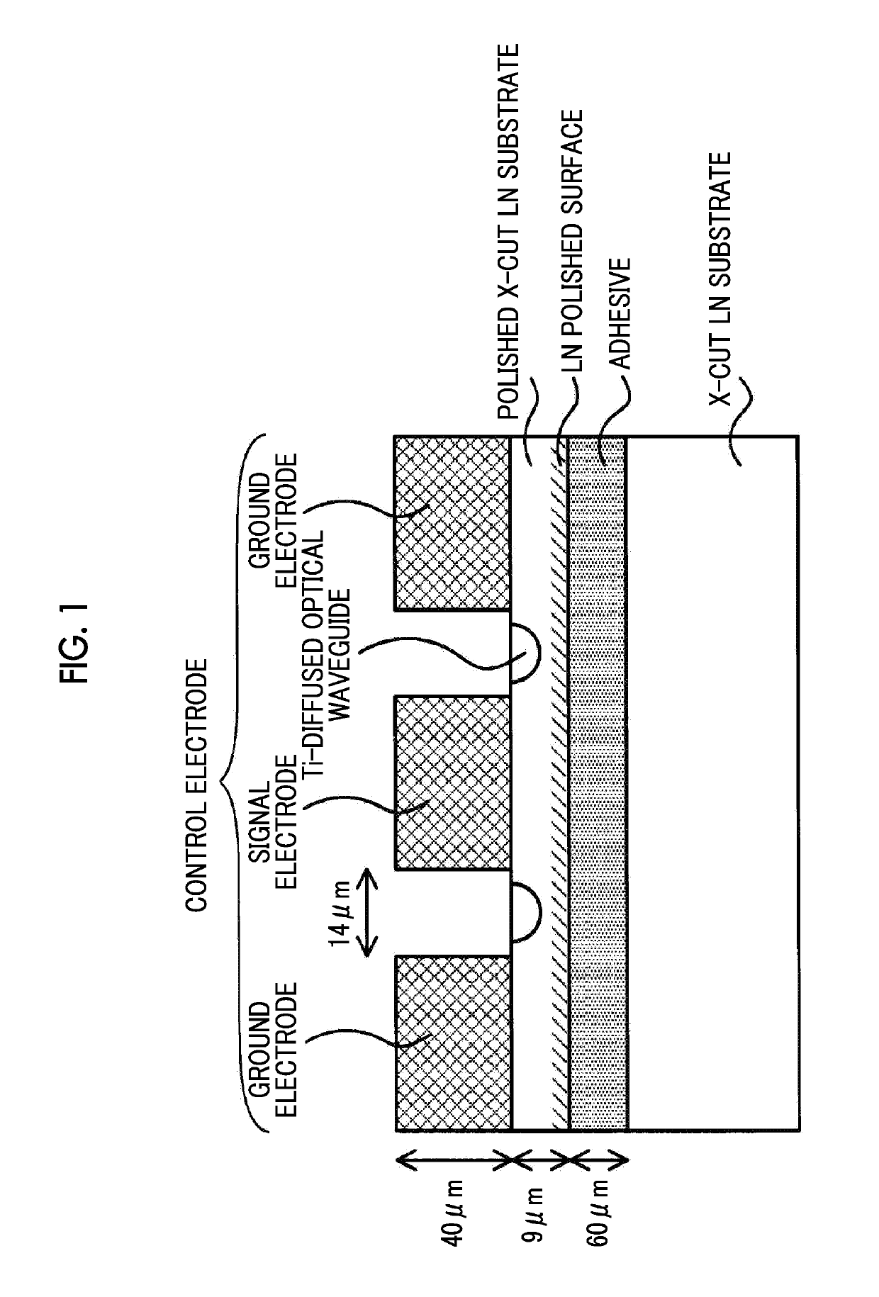
[0032]According to the invention, there is provided a thin-plate LN optical control device including: a thin-plate LN optical waveguide element which includes an optical waveguide formed by thermal diffusion of Ti and a control electrode configured to control a light wave propagating through the optical waveguide in a substrate made of lithium niobate, and in which at least a part of the substrate is thinned; and a housing that accommodates the thin-plate LN optical waveguide element in an air-tight sealing manner. Oxygen is contained in a filler gas inside the housing.

[0033]“Thinning” in the invention represents a state in which the thickness of at least a part of a substrate is made to be small by mechanical processing such as polishing and cutting. The “thinning” includes not only a state in which the entirety of the substrate is made to be thin but also a state in which a ridge...


PUM

PropertyMeasurementUnit
thicknessaaaaaaaaaa
thicknessaaaaaaaaaa
thicknessaaaaaaaaaa

Abstract

A thin-plate LN optical control device includes: a thin-plate LN optical waveguide element which includes an optical waveguide formed by thermal diffusion of Ti in a substrate made of lithium niobate, and a control electrode that is formed on the substrate and is configured to control a light wave propagating through the optical waveguide, and in which at least a part of the substrate is thinned; and a housing that accommodates the thin-plate LN optical waveguide element in an air-tight sealing manner. Oxygen is contained in a filler gas inside the housing.

Description

CROSS-REFERENCE TO RELATED APPLICATIONS[0001]This application claims the benefit of Japanese Patent Application No. 2016-241813 filed Dec. 14, 2016, the disclosure of which is herein incorporated by reference in its entirety.BACKGROUND OF THE INVENTION[0002]Field of the Invention[0003]The present invention relates to an LN optical control device including an LN optical waveguide element in which an optical waveguide and a control electrode configured to control a light wave that propagates through the optical waveguide are formed in a substrate that is formed by using lithium niobate (LN), and a housing that accommodates the LN optical waveguide element in an air-tight sealing manner, and particularly to, an LN optical control device (referred to as a thin-plate LN optical control device) that uses the LN optical waveguide element that is thinned.[0004]Description of Related Art[0005]In an optical communication field or an optical measurement field, there is known an optical control...

Claims


Application Information

Patent Timeline
Patent Type & Authority Patents(United States)
IPC IPC(8): G02B6/122G02F1/225G02B6/13G02B6/30G02B6/134G02F1/03G02F1/035
CPCG02F1/0316G02B6/122G02B6/13G02B6/1342G02F1/2257G02F1/03G02F1/035G02F1/0353G02F1/225G02B6/30G02F1/0305
Inventor KONDOU, KATSUTOSHINAKANO, KIYOTAKAMURAKAMI, EIJI
Owner SUMITOMO OSAKA CEMENT CO LTD
Why Eureka
Try Eureka