Cu—Ga—In—Na target

a target and cu-ga technology, applied in the field of sputtering targets, can solve the problems of reducing the homogeneity of the microstructure and the density of the target, reducing the quality of the deposited layer, and reducing the sputtering process. , to achieve the effect of good processability, high purity and low cos

Active Publication Date: 2019-06-25
PLANSEE SE
View PDF24 Cites 0 Cited by
  • Summary
  • Abstract
  • Description
  • Claims
  • Application Information

AI Technical Summary

Benefits of technology

[0009]The objective of the invention is to produce a sputtering target from a Cu—Ga—Na, a Cu—In—Na or a Cu—Ga—In—Na alloy with avoidance of the disadvantages mentioned. More particularly, an inventive sputtering target having high purity is to be provided, which has a homogeneous and fine-grain microstructure. The inventive sputtering target is to be producible inexpensively, have good processability and be easy to handle, and be achievable without the addition of organic compounds or salts.

Problems solved by technology

Sputtering targets produced by melt metallurgy show the disadvantage of a coarse microstructure which leads to relief formation in the sputtering process through inhomogeneous erosion.
A disadvantage of such an introduction of alkali metal atoms is contamination by the organic constituents used or cations of the salts used, which subsequently leads to a reduction in the homogeneity of the microstructure and in the density of the target.
This also reduces the quality of the deposited layer, and the desired optimal sputtering outcome is not achieved.
Moreover, the relatively low chemical stability of such alkali metal compounds leads to material losses during the production process, and accordingly to variations in the composition of the sputtering targets thus produced.
Subsequently, unwanted and performance-reducing inhomogeneities also arise in layers deposited with such sputtering targets.
For example, the hygroscopic properties of the salts introduced can cause an increased corrosion tendency of the target; consequently, targets produced in this way can only be processed dry.

Method used


Image

  • Cu—Ga—In—Na target
  • Cu—Ga—In—Na target

Examples


example 1

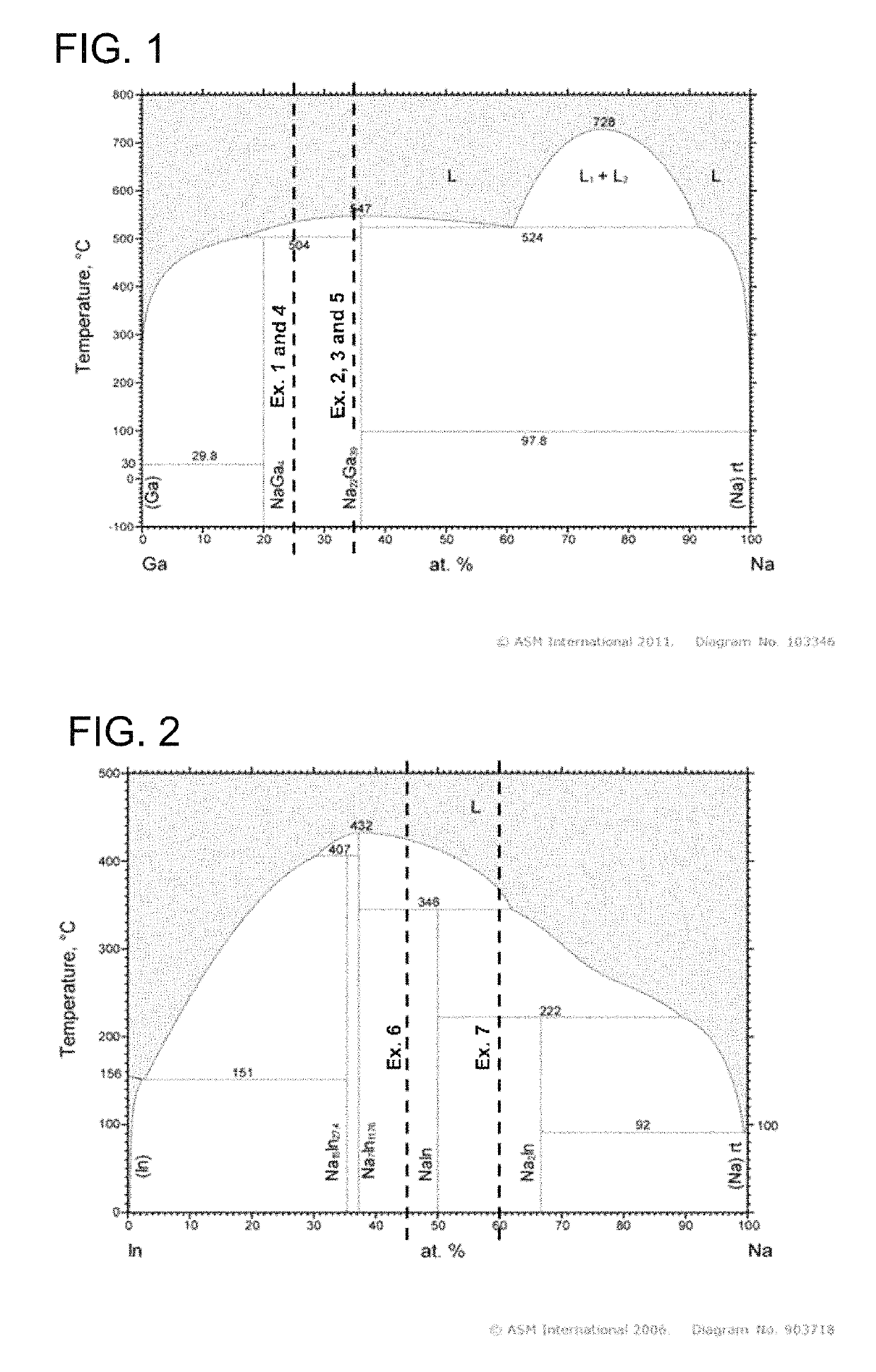
[0061]1 kg of Ga were heated to 200° C. and melted in a graphite crucible by means of induction heating. Subsequently, 0.1 kg of Na was added (ratio in at % Ga / Na=75 / 25). The temperature was subsequently increased to 600° C. After complete melting, the alloy was cast in a die made from hot-work steel.

[0062]After solidification, the ingot thus produced was removed and, after complete cooling, comminuted with the aid of a jaw crusher and a cross-beater mill.

[0063]Thereafter, the Ga—Na preliminary alloy powder thus obtained was screened off to a size of <500 μm and mixed with gas-atomized Cu—Ga alloy powder (Ga content 25 at %), such that an Na content of 1 at % was established.

[0064]The Cu—Ga—Na powder mixture thus obtained was compacted to a disc in a uniaxial hot press at a temperature of 400° C. and then processed to completion to give a sputtering target having a thickness of 5 mm and a diameter of 100 mm.

example 2

[0065]5 kg of Ga were heated to 200° C. and melted in a graphite crucible by means of induction heating. Subsequently, 0.9 kg of Na was added (ratio in at % Ga / Na=65 / 35). The temperature was subsequently increased to 600° C. After complete melting, the alloy was cast in a die made from hot-work steel.

[0066]After solidification, the ingot thus produced was removed and, after complete cooling, comminuted with the aid of a jaw crusher and a cross-beater mill.

[0067]Thereafter, the Ga—Na preliminary alloy powder thus obtained was screened off to a size of <500 μm and mixed with gas-atomized Cu—Ga alloy powder (Ga content 25 at %), such that an Na content of Sat % was established.

[0068]The Cu—Ga—Na powder mixture thus obtained was introduced into a tubular steel capsule, hot-degassed at 300° C. and sealed airtight. The powder was compacted by means of hot isostatic pressing at a temperature of 450° C., a pressure of 100 MPa.

[0069]The blank thus obtained was subsequently processed by means...

example 3

[0070]5 kg of Ga were heated to 200° C. in an Ar protective gas atmosphere and melted in a graphite crucible by means of induction heating. Subsequently, 0.9 kg of Na was added (ratio in at % Ga / Na=65 / 35). In the course of this, the temperature was increased to 600° C. After the alloy had melted completely, atomization was effected by means of Ar gas to a spherical preliminary alloy powder.

[0071]Subsequently, the preliminary alloy powder thus obtained was mixed with likewise gas-atomized Cu—Ga alloy powder (Ga content 30 at %) to give a Cu—Ga—Na powder mixture having an Na content of 1 at %.

[0072]The Cu—Ga—Na powder mixture thus obtained was compacted in a uniaxial hot press by means of spark plasma sintering (SPS) at a temperature of 400° C. to give a disc, and then processed to completion to give a disc-shaped sputtering target having a thickness of 5 mm and a diameter of 100 mm.


PUM

PropertyMeasurementUnit
melting pointsaaaaaaaaaa
aspect ratioaaaaaaaaaa
sizeaaaaaaaaaa

Abstract

A sputtering target is composed of an alloy consisting of 5 to 70 at % of at least one element from the group of (Ga, In) and 0.1 to 15 at % of Na, the remainder being Cu and typical impurities. The sputtering target includes at least one intermetallic Na-containing phase.

Description

BACKGROUND OF THE INVENTION[0001]A portion of the disclosure of this patent document contains material which is subject to copyright protection. The copyright owner has no objection to the facsimile reproduction by anyone of the patent document or the patent disclosure, as it appears in the Patent and Trademark Office patent file or records, but otherwise reserves all copyright rights whatsoever.Field of the Invention[0002]The invention relates to a sputtering target composed of an alloy consisting of 5 to 70 at % of at least one element from the group of (Ga, In) and 0.1 to 15 at % of Na, the remainder being Cu and typical impurities. The invention further relates to a process for producing a sputtering target and to the use thereof.[0003]Photoactive layers for thin-film solar cells are produced via physical vapour deposition (PVD) processes. These are coating processes in which the layer formation takes place through vaporization of the layer-forming particles from a target and th...

Claims


Application Information

Patent Timeline
Patent Type & Authority Patents(United States)
IPC IPC(8): C23C14/34C22C24/00H01J37/34H01L31/18C22C9/00C22C1/04C22C30/02B22F1/00B22F9/04C22C28/00B22F3/12B22F3/02B22F9/08B22F3/105B22F3/15
CPCC23C14/3414B22F1/00H01L31/18H01J37/3426C22C30/02C22C28/00C22C24/00C22C9/00C22C1/0491C22C1/0425B22F3/02B22F3/12B22F9/04B22F9/082B22F2998/10B22F2003/1051B22F3/15B22F3/10B22F3/20B22F3/18B22F3/17C22C1/047
Inventor LINKE, CHRISTIANLI, JIEHUASCHUMACHER, PETERKNABL, WOLFRAMLEICHTFRIED, GERHARD
Owner PLANSEE SE
Why Eureka
Try Eureka