Method and device for continuous dry methanation

a technology of methane and continuous dry methane, which is applied in the field of continuous dry methane, can solve the problems of inability to enable fermentation control that makes possible significant degradation of fermenting matter, and the line for intermittent injection of pressurized gas cannot cope with reflux, so as to reduce the dimensions of the fermenter and the duration of the fermentation

Active Publication Date: 2019-03-12
METHA ENR +1
View PDF7 Cites 0 Cited by
  • Summary
  • Abstract
  • Description
  • Claims
  • Application Information

AI Technical Summary

Benefits of technology

[0016]Thanks to these provisions, two media are created that are favorable to the different phases of the fermentation and, as a result, the dimensions of the fermenter and the duration of the fermentation are reduced.

Problems solved by technology

But the known mixing methods, in at least two compartments, do not let slurry close to shear thresholds flow; and they are not suitable for allowing the matter to be stirred in the entirety of a given volume; and they cannot enable control of the fermentation that makes possible significant degradation of the fermenting matter in short retention times and without significant dilution of the matter.
The lines for intermittently injecting pressurized gas cannot cope with any reflux of matter, which can block the injectors, in the gas pipes.
The tip of the injector is necessarily narrow, generating a narrow upwards gas jet that can have only a limited effect on the stirring of slurry; during gas injections this creates preferential passages in the matter that limit the stirring and turning over thereof, in particular for matter at the bottom of the tank, thus making it difficult to put heavy elements back in suspension, with the risk of these accumulating at the bottom of the fermenter.
The insufficient stirring thus makes the flow of matter more difficult with phase separations creating dead zones and different fermentation speeds in the fermenter.

Method used


Image

  • Method and device for continuous dry methanation
  • Method and device for continuous dry methanation
  • Method and device for continuous dry methanation

Examples


Embodiment Construction

[0054]After having noted that the figures are not to scale, and before describing the figures in more detail, a description of characteristics of particular embodiments of the method and device that are the subjects of the present invention is given below.

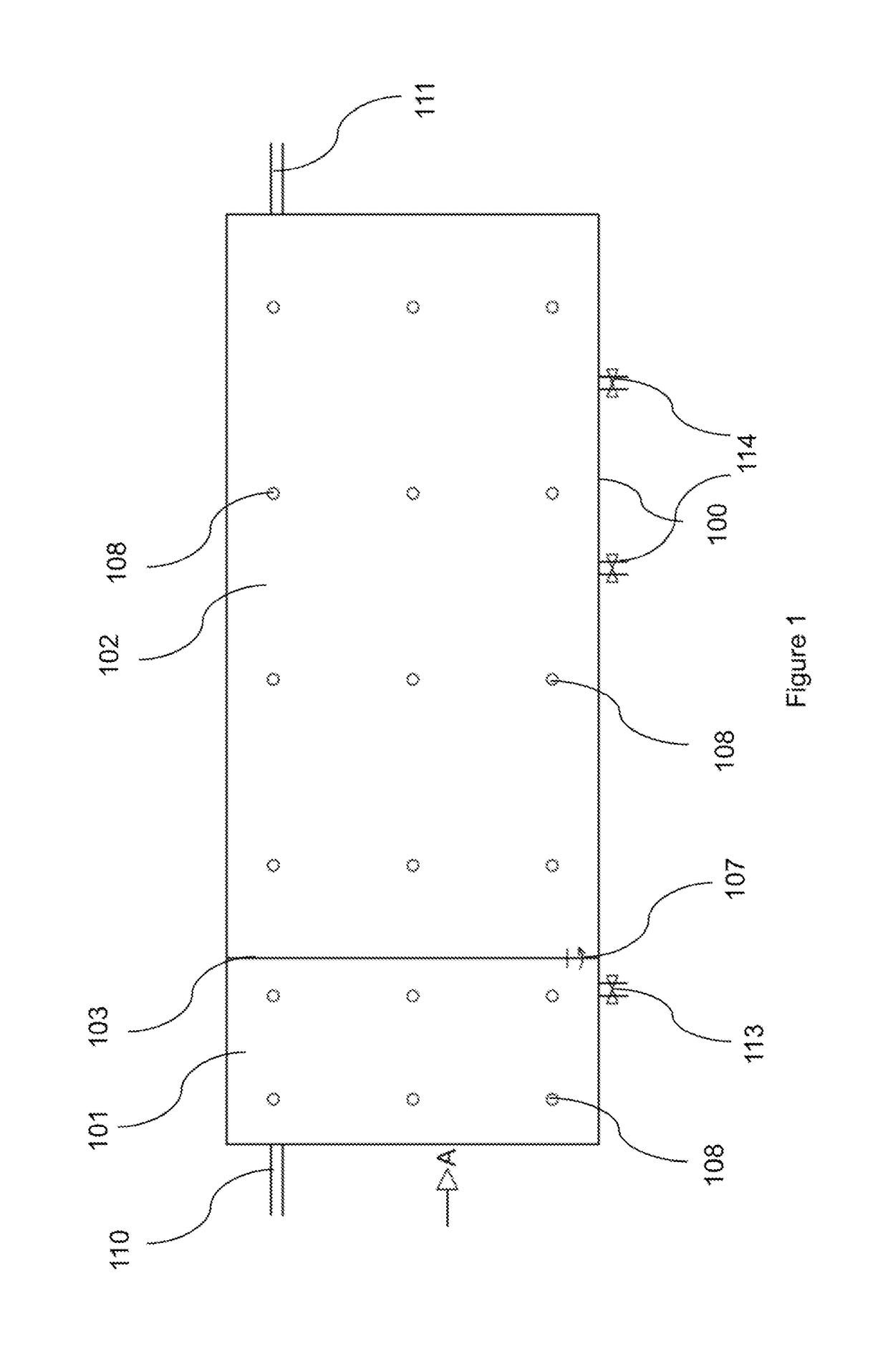
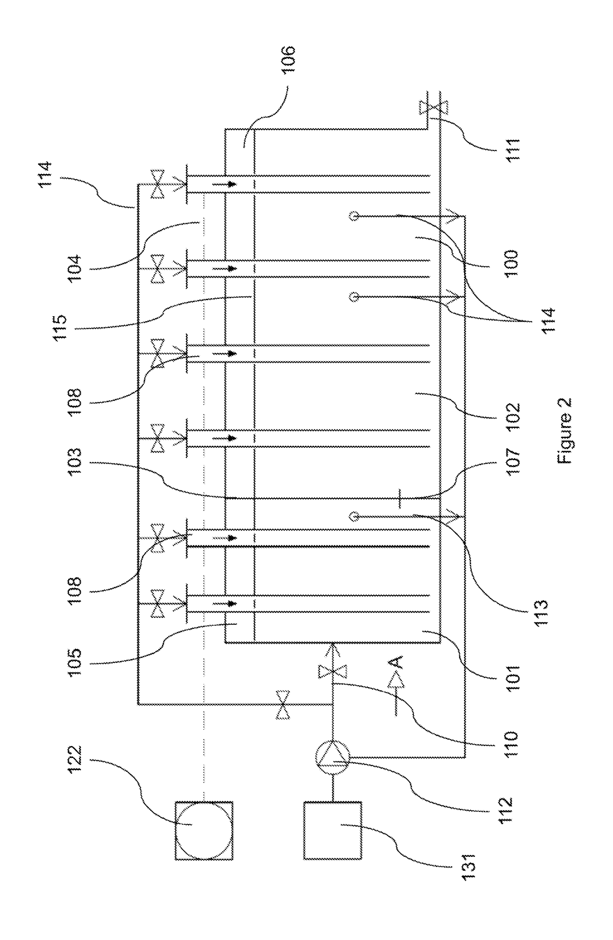
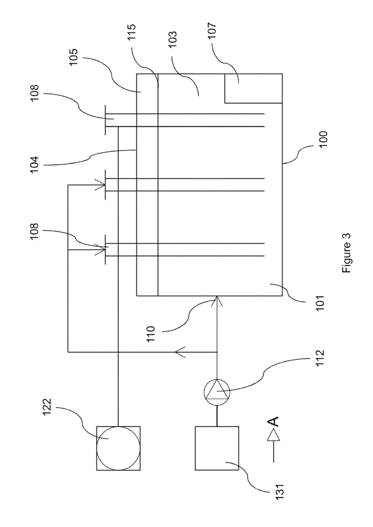
[0055]Continuous methanation of slurry is carried out in a compartmented vessel at two temperature and pH levels, based on a sector-modifiable stirring, according to the viscosity of the fermenting matter, by injecting gas at high speeds and flow rates, in several chimneys. The configuration of these creates a broad convective movement starting from the bottom of the fermenter, drawing the matter over a large surface.

[0056]The mixing of a slurry is preferably sectoral. The stirring of a matter close to the flow thresholds by injecting pressurized gas presents limits. The limits encountered in the prior state of the art are of two types, depending on whether the substrates are diluted or one operates in a mode called dry or slurry:[...


PUM

PropertyMeasurementUnit
diameteraaaaaaaaaa
diameteraaaaaaaaaa
flow rateaaaaaaaaaa

Abstract

A device for continuous dry methanation in a fermenter having a closed tank having at least one compartment to ferment the slurry comprising at least 17% dry matter. An injector to inject pressurized gas close to the bottom of the compartment via at least one chimney that descends through the compartment. The injected gas rising through the slurry creates a convective movement in the slurry around the chimney to stir the matter at the bottom of the compartment. The tank can include a first compartment into which the slurry is introduced and a second compartment into which the hydrolyzed slurry flows after hydrolysis and acidogenesis in the first compartment. Methanogenesis takes place in the second compartment.

Description

RELATED APPLICATIONS[0001]This application is a § 371 application from PCT / FR2013 / 051938 filed Aug. 13, 2013, which claims priority from French Patent Application No. 1257782 filed Aug. 13, 2012, No. 1262512 filed Dec. 20, 2012, No. 1262513 filed Dec. 20, 2012, No. 1262514 filed Dec. 20, 2012, each of which is herein incorporated by reference in its entirety.TECHNICAL FIELD OF THE INVENTION[0002]This invention concerns a method and a device for continuous dry methanation. It applies in particular to continuous dry methanation in compartments with different physical and biochemical media, by sectoral stirring, at a modifiable high flow rate of gas.BACKGROUND OF THE INVENTION[0003]Anaerobic fermentation of effluents and waste aims to reduce organic matter and produce energy in the form of biogas. The methanation of sludge in liquid phase coming from the effluent treatment by urban wastewater purification stations, the methanation of the fermentable portion of household waste and the m...

Claims


Application Information

Patent Timeline
Patent Type & Authority Patents(United States)
IPC IPC(8): C12P5/02C12M1/00C12M1/107C12M1/02C12M1/34C12M1/16
CPCC12P5/023C12M21/04C12M21/16C12M23/34C12M29/06C12M29/14C12M29/24C12M41/00C12M41/18C12M41/26C12M45/09C12M29/18Y02E50/343Y02E50/30
Inventor BONHOMME, MICHEL
Owner METHA ENR
Why Eureka
Try Eureka