Vibrating diaphragm assembly
a diaphragm and vibration technology, applied in the field of electroacoustics, can solve the problems of poor strength and uniformity, difficult molding and processing of diaphragms composed of single-layer polymer materials, and general problems of diaphragms composed of the materials described above, so as to improve the reliability yield of products, wide temperature adaptability range, and strong temperature resistance
- Summary
- Abstract
- Description
- Claims
- Application Information
AI Technical Summary
Benefits of technology
Problems solved by technology
Method used
Image
Examples
embodiment 1
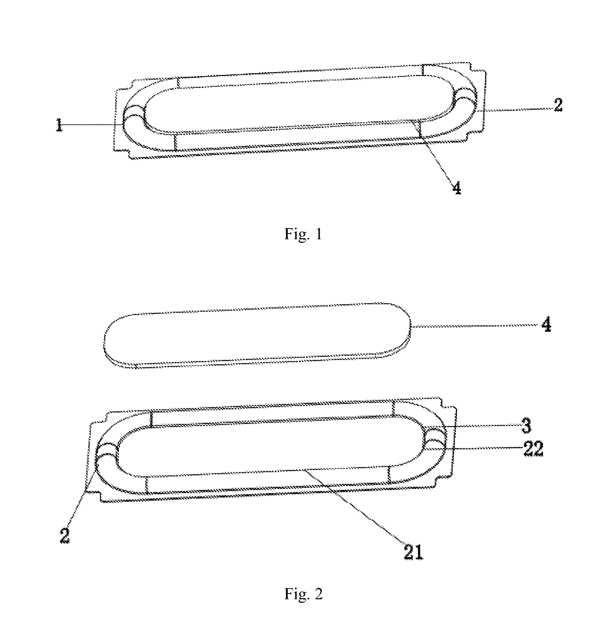
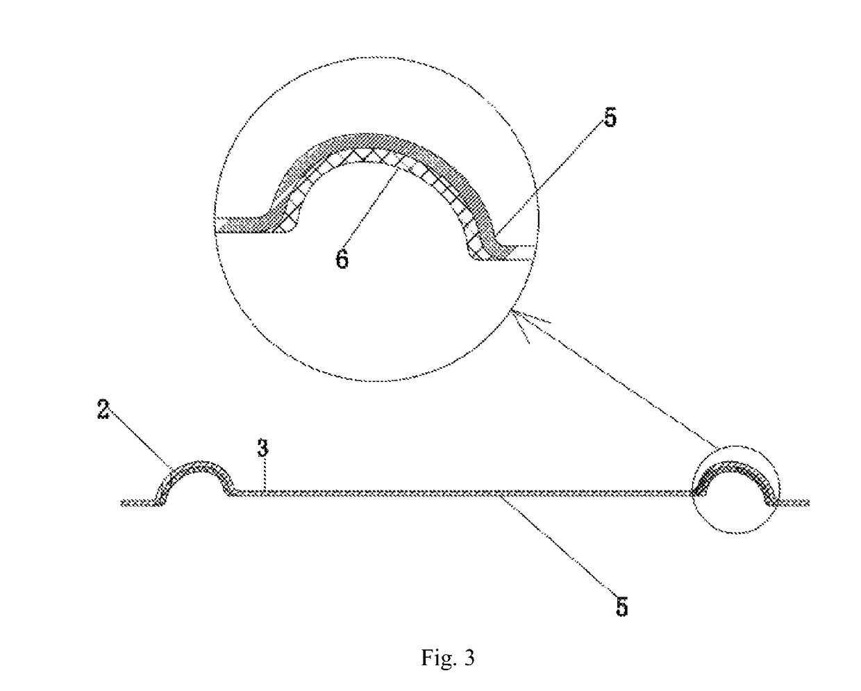
[0028]FIGS. 1-3 illustrate a diaphragm assembly structure according to embodiment 1 of the present invention. In the present embodiment, a diaphragm base layer is a single polymer material layer, and a middle portion of a diaphragm is a diaphragm base layer.
[0029]As shown in FIGS. 1-3, the diaphragm assembly comprises a diaphragm 1, wherein the diaphragm 1 comprises a middle portion 3 and a surround portion 2 which encircles the periphery of the middle portion 3. The diaphragm assembly further comprises a reinforcing portion 4 arranged in the middle of the diaphragm 1. The reinforcing portion 4 is integrated to an upper side or a lower side of the middle portion 3 and is generally of a single-layer structure or multi-layer structure composed of polyether ether ketone (PEEK), thermoplastic polyurethane elastomer (TPU) or other polymer materials.
[0030]The diaphragm 1 comprises a diaphragm base layer 5 and a silica gel layer 6 integrated to the surface of the surround portion 2. The di...
embodiment 2
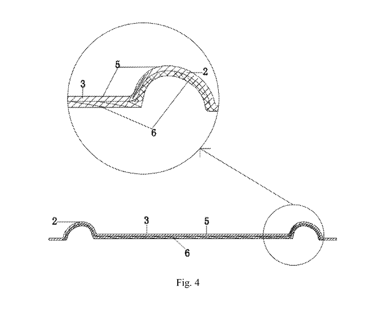
[0038]FIG. 4 illustrates the second embodiment of the diaphragm of the present invention, which is basically the same as embodiment 1. The difference therebetween lies in that: the middle portion 3 of the diaphragm 1 is of a composite structure of the diaphragm base layer 5 and the silica gel layer 6, that is, the silica gel layer 6 is integrated to both the surfaces of the surround portion 2 and the middle portion 3 by injection molding.
embodiment 3
[0039]FIG. 5 illustrates the third embodiment of the diaphragm of the present invention, which is basically the same as embodiment 1. The difference therebetween lies in that: the diaphragm base layer 5′ is a two-layer polymer material layer, including a polyether ether ketone (PEEK) material layer 7 and a thermoplastic polyurethane elastomer (TPU) material layer 8. It should be pointed out that the polymer material layers are not limited to the two material layers described above, and may also be composed of any two materials selected from a group including polyethylene terephthalate (PET), polyethylene naphthalate (PEN), polyether ether ketone (PEEK), polyetherimide (PEI), polyphenylene sulfide (PPS), polyarylate (PAR), thermoplastic polyurethane elastomer (TPU). It should be noted that, in a specific implementation, the diaphragm base layer 5′ is not limited to the materials described above, and other polymer materials may be used as the diaphragm base layer.
[0040]As shown in FIG...
PUM
| Property | Measurement | Unit |
|---|---|---|
| thickness | aaaaa | aaaaa |
| thickness | aaaaa | aaaaa |
| shape | aaaaa | aaaaa |
Abstract
Description
Claims
Application Information
 - R&D
- Intellectual Property
- Life Sciences
- Materials
- Tech Scout
- Unparalleled Data Quality
- Higher Quality Content
- 60% Fewer Hallucinations
Browse by: Latest US Patents, China's latest patents, Technical Efficacy Thesaurus, Application Domain, Technology Topic, Popular Technical Reports.
© 2025 PatSnap. All rights reserved.Legal|Privacy policy|Modern Slavery Act Transparency Statement|Sitemap|About US| Contact US: help@patsnap.com


