Inductively coupled plasma ion source with tunable radio frequency power
a plasma ion source and radio frequency power technology, applied in plasma techniques, accelerators, electric discharge tubes, etc., can solve the problems of limiting the usefulness of removing volumes with dimensions exceeding 10 m, spherical aberration and beam size dramatically increasing, and achieve high voltage isolation and improved magnetic filtering
- Summary
- Abstract
- Description
- Claims
- Application Information
AI Technical Summary
Benefits of technology
Problems solved by technology
Method used
Image
Examples
first embodiment
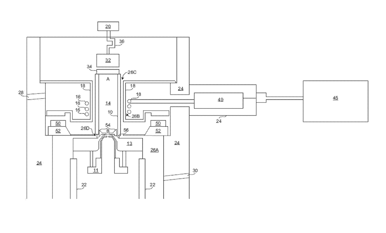
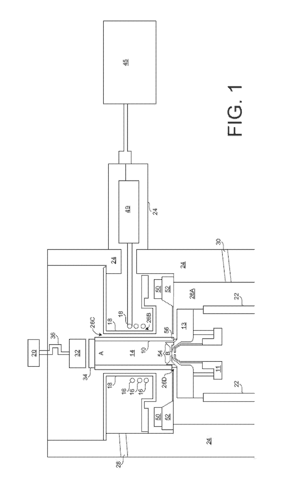
[0050]FIG. 5 illustrates an impedance matching network 49 used in association with the plasma ion source shown in FIG. 1. This impedance matching network 49 is incorporated into a lateral projection of a generally cylindrical source enclosure or can 24 (FIG. 1) into which the antenna coil 16 is placed. The load and tune capacitors of the impedance matching network 49 each include a main fixed capacitor 86f, 88f, respectively, coupled in parallel with a respective trim capacitor 86t, 88t. In the case that the capacitance of the “fixed” capacitors 86f, 88f are not exactly fixed on the value advertised, e.g. that a labelled “100 μf capacitor” is actually 99.6 μf, the supplemental trim capacitors can be incorporated to bring the circuit up to the specified 100 μf. In this way, the network 49 can impart capacitance with high precision since the trim capacitors 86t, 88t can be adjusted to bring the fixed capacitors 86f, 88f to their needed values. Impedance matching network 49 is then cou...
second embodiment
[0051]FIG. 6 illustrates an impedance matching network 49 used in association with the plasma ion source shown in FIG. 1. This embodiment is much like that shown in FIG. 5, but has much of the RF power source 45 located against the source enclosure and sharing contact with the cooling fluid.
[0052]The ‘output’ shown in FIG. 6 is the same connection as is satisfied by the coax cable and the RF connector 90 in FIG. 5, and the ‘ground’ connection in FIG. 6 is the same as item 24 in FIG. 1. In the embodiment shown in FIG. 1, the RF signal is fed into the matchbox (49) via the central wire of the coax cable. The outer shield of the coax cable (which is connected to item 24) carries the return current to the RF generator. Item 24 is at ground potential and is connected to the outer shield of the coax cable.
[0053]In the embodiment shown in FIG. 6, there's no need for a coax cable or the coax cable connector (90), and instead the RF generator is directly attached to the match circuit, where ...
PUM
 Abstract
Description
Claims
Application Information
 - R&D
- Intellectual Property
- Life Sciences
- Materials
- Tech Scout
- Unparalleled Data Quality
- Higher Quality Content
- 60% Fewer Hallucinations
Browse by: Latest US Patents, China's latest patents, Technical Efficacy Thesaurus, Application Domain, Technology Topic, Popular Technical Reports.
© 2025 PatSnap. All rights reserved.Legal|Privacy policy|Modern Slavery Act Transparency Statement|Sitemap|About US| Contact US: help@patsnap.com


