
Method for nitriding a component of a fuel injection system

a fuel injection system and component technology, applied in the direction of mechanical equipment, solid-state diffusion coating, machines/engines, etc., can solve the problems of brittleness and thus also be very susceptible to cavitation stresses, and achieve the effect of reducing cavitation damage, increasing ductility (toughness), and positive effect on pulsating fatigue strength

Active Publication Date: 2018-11-13
ROBERT BOSCH GMBH
View PDF16 Cites 0 Cited by
  • Summary
  • Abstract
  • Description
  • Claims
  • Application Information

AI Technical Summary

Benefits of technology

The invention provides a nitriding method that reduces damage to components caused by high pressures. This is achieved by increasing ductility or toughness below the surface of the material. Nitriding also improves pulsating fatigue strength, increasing the life and endurance of components.

Problems solved by technology

Although the white layer is very hard, it is, at the same time, very brittle and hence also very susceptible to cavitation stresses.

Method used


Image

  • Method for nitriding a component of a fuel injection system
  • Method for nitriding a component of a fuel injection system
  • Method for nitriding a component of a fuel injection system

Examples


Embodiment Construction

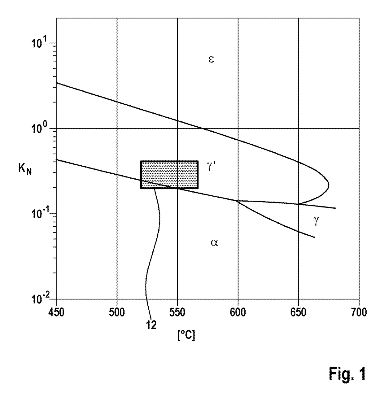
[0027]FIG. 1 shows a Lehrer diagram: the various state phases of the iron-nitrogen system of a component are shown as a function of temperature T and nitriding potential KN. The nitriding potential KN is plotted logarithmically against the nitriding temperature T. The Lehrer diagram does not show the nitriding time but it is generally in a range of between 1 hour and 100 hours.

[0028]The nitriding potential KN is defined as

[0029]KN=p⁡(NH3)p⁡(H2)3 / 2

[0030]Here, p(NH3) is the partial pressure of the ammonia and p(H2) is the partial pressure of the hydrogen. The partial pressure is in each case the pressure in an ideal gas mixture, which is associated with an individual gas component. This means that the partial pressure corresponds to the pressure which the individual gas component would exert in the relevant volume if it were present in isolation. The partial pressure is generally used instead of the mass concentration when the diffusion behavior of the dissolved gas is being considere...


PUM

PropertyMeasurementUnit
depthaaaaaaaaaa
depthaaaaaaaaaa
temperatureaaaaaaaaaa

Abstract

The invention relates to a method for nitriding a component of a fuel injection system, said component being loaded under high pressure and being composed of an alloyed steel. The method comprises the following steps: —activating the component in inorganic acid, —pre-oxidizing the component in oxygen-containing atmosphere between 380° C. and 420° C., —nitriding the component between 520° C. and 570° C. at a high first nitriding potential KN,1 in theε nitride range, —nitriding the component between 520° C. and 570° C. at a lower second nitriding potential KN,2 in the γ′ nitride range.

Description

BACKGROUND OF THE INVENTION[0001]The invention relates to a method for nitriding a component of a fuel injection system, said component being subject to high pressure and being composed of an alloyed steel.[0002]German Laid-Open Application DE 102 56 590 A1 discloses that an injection nozzle of a fuel injection system is very robust if the injection nozzle is in a nitrided state. In this case, corrosion resistance and wear resistance, in particular, are enhanced. However, no details are given of the nitriding method per se in this publication.[0003]WO publication WO 2001 / 042528 A1 has furthermore disclosed a method for nitriding an injection nozzle. The known nitriding method comprises a nitrocarburizing process in a salt bath in a first step, followed, in a second step, by a gas nitriding process at a temperature between 520° C. and 580° C. with a low nitriding index or low nitriding potential (in a range between 0.08 and 0.5), i.e. in the “a range” of the Lehrer diagram.[0004]The ...

Claims


Application Information

Patent Timeline
Patent Type & Authority Patents(United States)
IPC IPC(8): C23C8/26F02M61/16C23C8/34C23C8/02F02M61/10
CPCF02M61/168C23C8/02C23C8/26F02M61/10F02M61/166C23C8/34F02M2200/9038
Inventor PAULUS, CHRISTIANWERGER, HEINRICH
Owner ROBERT BOSCH GMBH
Learn More