
Combustion system having improved temperature resistance

a combustion system and temperature resistance technology, applied in the direction of solar heat systems, solid fuel combustion, lighting and heating apparatuses, etc., can solve the problems of significant thermal losses, significant thermomechanical stresses, and a very considerable thermal gradient between

Inactive Publication Date: 2018-10-16
COMMISSARIAT A LENERGIE ATOMIQUE ET AUX ENERGIES ALTERNATIVES
View PDF20 Cites 0 Cited by
  • Summary
  • Abstract
  • Description
  • Claims
  • Application Information

AI Technical Summary

Benefits of technology

[0008]It is consequently an aim of the present invention to offer a combustion system comprising a combustion chamber of at least one combustible gas and one oxidizing gas offering improved temperature resistance.
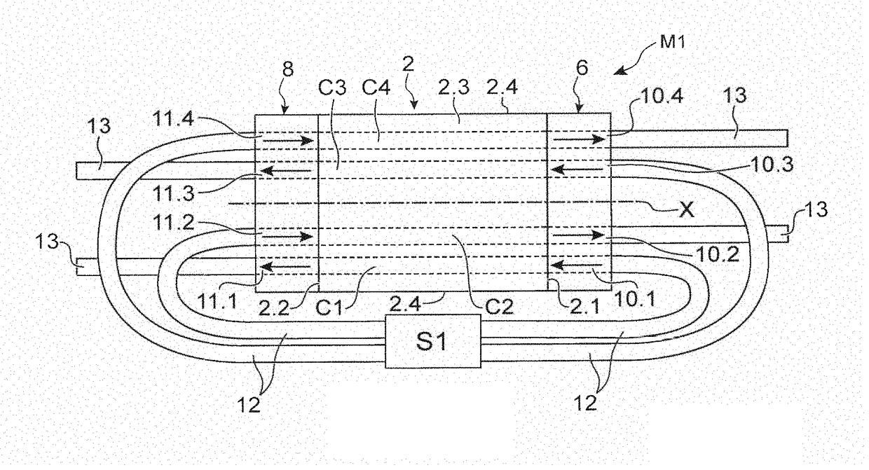
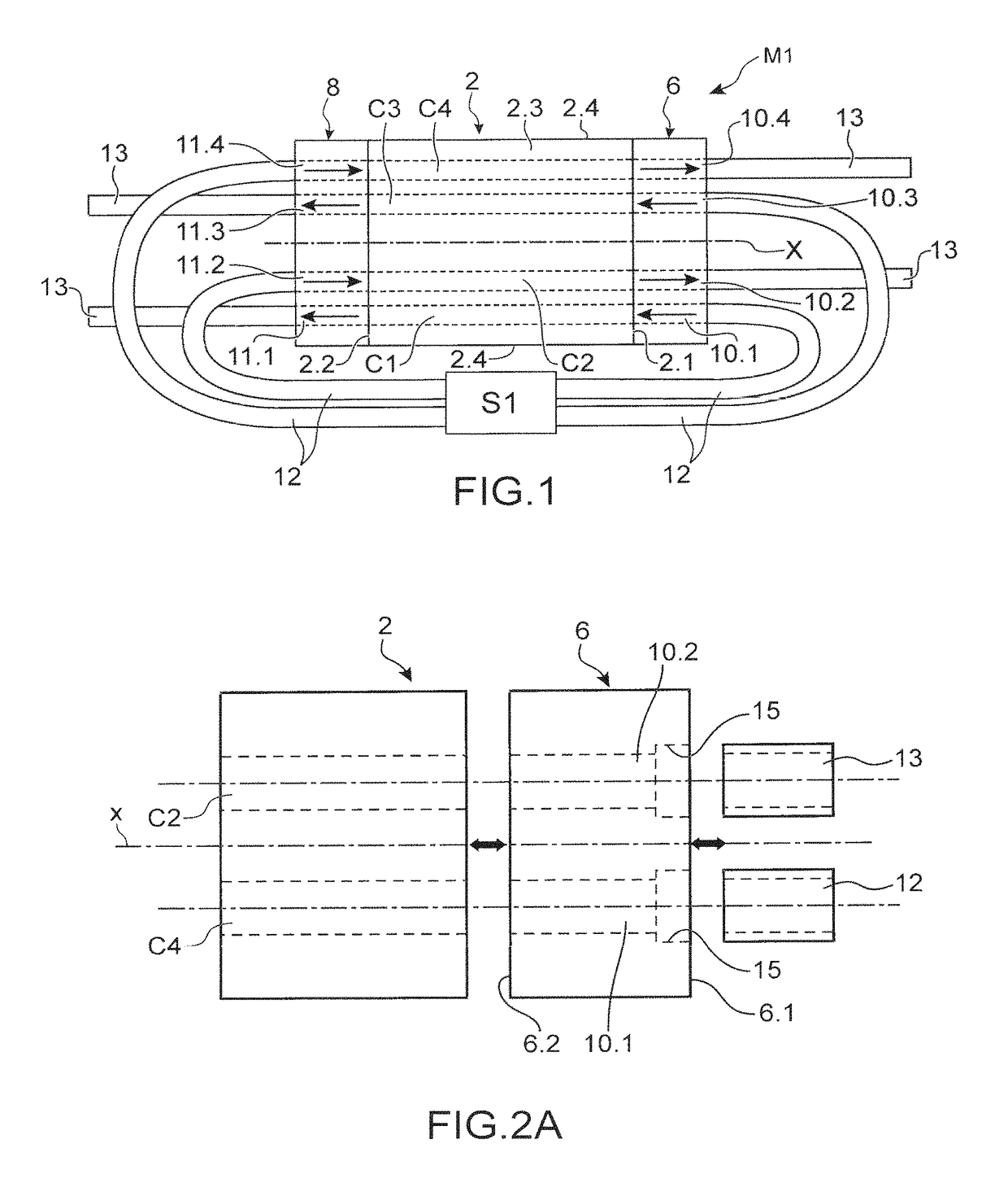
[0010]Thanks to the invention, by implementing connectors made of heat insulating material, stresses at the ends of the body of the module are reduced and, by imposing a circulation both of combustible gas and oxidizer and of combustion gas in each connector, the thermal gradient within the connectors is reduced, which reduces the thermomechanical stresses imposed on the connectors and thus reduces the risk of fissures of one and / or the other of the connectors.
[0011]Advantageously, each end of the chamber comprises several supply inlets and several supply outlets as well as connectors, the inlets and outlets being spread out so that at least two outlets surround two inlets and vice versa, which makes it possible to further limit the thermal gradient in the connectors.
[0012]In other words, both the cold gas or gases intended for combustion and the hot gases stemming from combustion are made to circulate in each of the connectors, which makes it possible to reduce the thermal gradient compared to that imposed on a connector intended solely for supply in the case where the combustion chamber comprises one end only comprising supply orifices and one end only comprising orifices intended for evacuation.

Problems solved by technology

Yet the supply and evacuation pipes, which are generally made of metal, more particularly steel, may be the source of significant thermal losses.
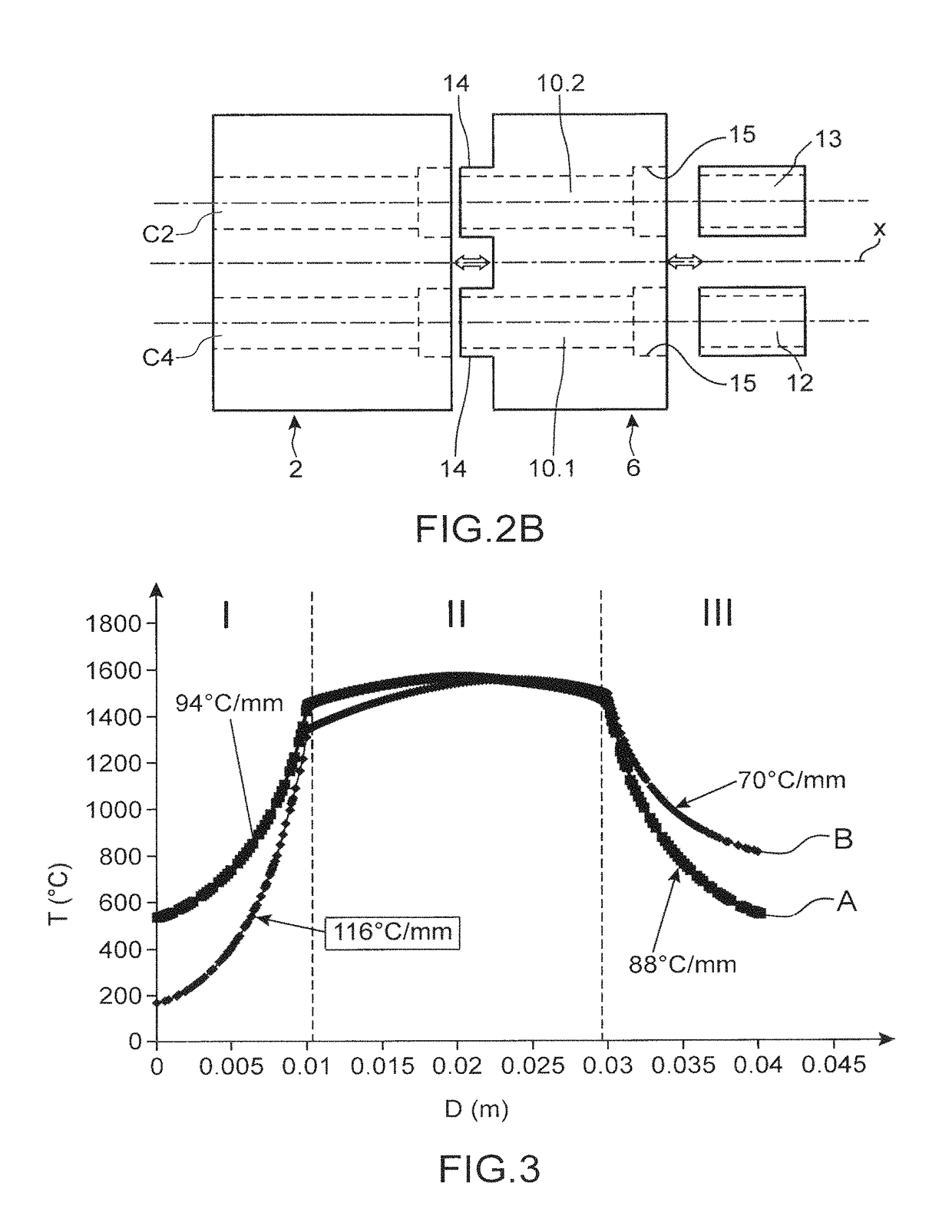
In addition, there exists a very considerable thermal gradient between the temperature of supply with combustible gas and the temperature of the module.
Yet this thermal gradient generates significant thermomechanical stresses and may pose problems of thermomechanical resistance.

Method used


Image

  • Combustion system having improved temperature resistance
  • Combustion system having improved temperature resistance
  • Combustion system having improved temperature resistance

Examples


Embodiment Construction

[0008]It is consequently an aim of the present invention to offer a combustion system comprising a combustion chamber of at least one combustible gas and one oxidizing gas offering improved temperature resistance.

[0009]The aforementioned aim is attained by a combustion system comprising at least one combustion module including at least one combustion chamber and one first end, at least one supply inlet and at least one evacuation outlet, and at a second end at least one supply inlet and at least one evacuation outlet, one first connector made of heat insulating material arranged at the first end and comprising at least one supply conduit and one evacuation conduit connected respectively to the supply inlet and to the evacuation outlet of the first end of the module, a second connector made of heat insulating material arranged at the second end and comprising at least one supply conduit and at least one evacuation conduit connected respectively to the supply inlet and to the evacuati...


PUM


Abstract

A combustion system is provided, including at least one combustion module and at least one source of combustible gas and oxidizing gas, the combustion module including a body including a single solid piece of material including two combustion chambers configured to be supplied with the at least one combustible gas and said one oxidizing gas; a first connector in contact with a first end of the body and being heat insulating, including first supply conduits configured to supply a combustible gas to the two combustion chambers, and first evacuation conduits configured to evacuate combustion gas from the two combustion chambers; and a second connector in contact with a second end of the body and being heat insulating, including second supply conduits configured to supply a combustible gas and an oxidizing gas to the two combustion chambers, and second evacuation conduits configured to evacuate combustion gas from the two combustion chambers.

Description

TECHNICAL FIELD AND PRIOR ART[0001]The present invention relates to a combustion system having improved temperature resistance and to a hybrid solar system comprising at least one such combustion module.[0002]Electricity production devices exist comprising a combustion module and a thermoelectric module, the hot face of the thermoelectric module being in contact with one of the faces of the combustion module. By burning one or more gases in the combustion module, the face of the thermoelectric module in contact with the combustion module is heated, a temperature gradient appears in the thermoelectric module, there is then production of electricity.[0003]An example of such a device is described in the document U.S. Pat. No. 7,862,331.[0004]The combustion module comprises a chamber supplied with gas via at least one supply pipe, the combustion gases are evacuated via at least one evacuation conduit.[0005]The material of the module has very good thermal conductivity since it is desired...

Claims


Application Information

Patent Timeline
Patent Type & Authority Patents(United States)
IPC IPC(8): H01L35/30F24S20/20F23C3/00F23B10/00F23M5/00F24S20/40
CPCH01L35/30F23B10/00F23C3/002F24S20/20F24S20/40F23M5/00Y02E10/41Y02E10/40H10N10/13
Inventor OLLIER, EMMANUELMANTZARAS, IOANNIS
Owner COMMISSARIAT A LENERGIE ATOMIQUE ET AUX ENERGIES ALTERNATIVES
Learn More