
Low impact threat rupture device for explosive ordnance disruptor

a technology of explosive ordnance disruptor and low impact threat, which is applied in the field of explosive ordnance disposal (eod), can solve the problems of explosive ordnance explosions that are far more violent and lethal, and pressure and shock waves that are produced

Active Publication Date: 2018-09-04
THE UNITED STATES OF AMERICA AS REPRESENTED BY THE SECRETARY OF THE NAVY
View PDF9 Cites 9 Cited by
  • Summary
  • Abstract
  • Description
  • Claims
  • Application Information

AI Technical Summary

Benefits of technology

The invention is an apparatus for disrupting explosive devices. It includes an EOD disruptor with a barrel and a blank cartridge. A water column is placed in front of the blank cartridge, and a water plug is placed in front of the water column. The apparatus also includes a muzzle-loaded projectile with a shaft portion and a front portion. The shaft portion is placed in the barrel and may have a sub-caliber diameter. The projectile may also have a restraint system to limit its travel. The method involves firing the projectile with a muzzle velocity of less than 1000 feet per second. The technical effects of this invention include improved safety and reliability in disrupting explosive devices.

Problems solved by technology

The unexpected consequences of this approach are the tremendous pressures and shock waves that are produced.
For example, after projectile impact, black powder inside an IED can be compressed and heated to ignition, resulting in an IED exploding and fragmenting.
The RSP creates an explosion that is far more violent and lethal than if the IED simply functioned as designed.
Even so, such conventional technology cannot pierce, for example, 2 inch diameter schedule 40 steel cased pipe bombs.

Method used


Image

  • Low impact threat rupture device for explosive ordnance disruptor
  • Low impact threat rupture device for explosive ordnance disruptor
  • Low impact threat rupture device for explosive ordnance disruptor

Examples


Embodiment Construction

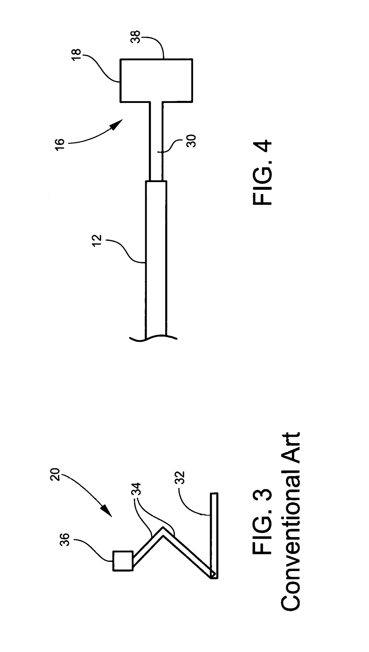
[0022]FIGS. 1 and 2 show an EOD disruptor 10. In one exemplary embodiment, disruptor 10 is a 12 gauge PAN disruptor having a barrel 12 and a breech 14. The disruptor 10 may be mounted to a known fixed mount stand 20 (FIG. 3). The disruptor 10 may tolerate breech pressures in excess of 50,000 psi. Stand 20 may include a base portion 32, articulating arms 34 and a mount 36. A 12 gauge blank cartridge 22 may be loaded in breech 14 of disruptor 10. A water column 24 may be disposed in the barrel 12 in front of the blank cartridge 22. A water plug or wadding 26 may be disposed in front of the water column 24. A muzzle-loaded projectile 16 may be disposed in front of the water plug 26.

[0023]Projectile 16 may be made of, for example, steel, tungsten, metal alloys, and composites. Different portions of the projectile 16 may be made of different materials. The projectile 16 includes a generally cylindrical shaft portion 30 at least partially disposed in the barrel 12 and a front portion 18 d...


PUM


Abstract

An EOD disruptor system for penetrating steel encased explosive devices has a barrel and a blank cartridge loaded in the EOD disruptor. A water column is disposed in the barrel in front of the blank cartridge. A water plug is disposed in front of the water column. A muzzle-loaded projectile is disposed in front of the water plug. The projectile includes a shaft portion at least partially disposed in the barrel and a front portion disposed outside of the barrel. The shaft portion may have a length from about four inches to about eighteen inches. The projectile may have a weight from about four ounces to about two pounds. The ratio of the length of the shaft portion of the projectile to the inner barrel diameter may be in a range of about two to about 50.

Description

STATEMENT OF GOVERNMENT INTEREST[0001]The invention described herein may be manufactured and used by or for the Government of the United States of America for Governmental purposes without the payment of any royalties thereon or therefor.FIELD OF THE INVENTION[0002]The invention relates in general to explosive ordnance disposal (EOD) and in particular to projectiles for EOD disruptors, including but not limited to percussion activated non-electric (PAN) disruptors and electrically initiated EOD disruptors.BACKGROUND OF THE INVENTION[0003]Some known improvised explosive device (IED) threats and newly emerging IED threats use steel-cased devices containing thermal and / or impact sensitive propellants or thermal or impact sensitive explosives. Currently used render safe procedures (RSPs) carried out with gun-type EOD disruptors use high velocity steel or other metal or metal composite projectiles moving in excess of 2000 fps to vent hard cased IEDs. The unexpected consequences of this a...

Claims


Application Information

Patent Timeline
IPC IPC(8): F42B12/74F42D5/04F42B33/06F42B8/04
CPCF42B33/067F42B12/74F42B8/04F42D5/04F41H11/12F42B12/02F42B12/82
Inventor VABNICK, IANELLIS, ARTHURROTHENBERGER, JOESMITH, CHADSHARP, MIKEFOLTZ, LEEMOREFIELD, ERICBLACK, BARRY
Owner THE UNITED STATES OF AMERICA AS REPRESENTED BY THE SECRETARY OF THE NAVY
Learn More