Vacuum fusion welding packaging method and packaging device

A packaging device and packaging method technology, applied in welding equipment, resistance welding equipment, metal processing equipment, etc., can solve the problems of hindering the vibration of the vibrator, reducing the quality of the product, and low welding yield, so as to achieve easy packaging operation and high yield , The effect of short welding time

Inactive Publication Date: 2007-04-25
甘志银
View PDF0 Cites 13 Cited by
  • Summary
  • Abstract
  • Description
  • Claims
  • Application Information

AI Technical Summary

Problems solved by technology

However, for the packaging of certain devices such as accelerometers or gyroscopes and MEMS (micro-electromechanical systems) devices such as radio frequency, inertial, and mechanical resonators, if it is only hermetically sealed, there will be residual gas in the device cavity such as Air or nitrogen will hinder the vibration of its vibrator, thereby affecting its sensitivity and greatly reducing the quality of the product
There is also a vacuum packaging method. The existing vacuum packaging method is a reflow soldering process with solder, that is, the prefabricated solder ring is placed between the tube base and the tube cap, positioned and pressed by the mold, and heated in a vacuum box. Soldering, this vacuum packaging method, on the one hand, because the tube base is pre-compressed, it is difficult to achieve a low vacuum in the tube base; on the other hand, reflow soldering requires a variety of factors such as a suitable soldering temperature curve and controlling the thickness of the solder , difficult to master, low welding yield

Method used


Image

  • Vacuum fusion welding packaging method and packaging device
  • Vacuum fusion welding packaging method and packaging device

Examples


Embodiment 1

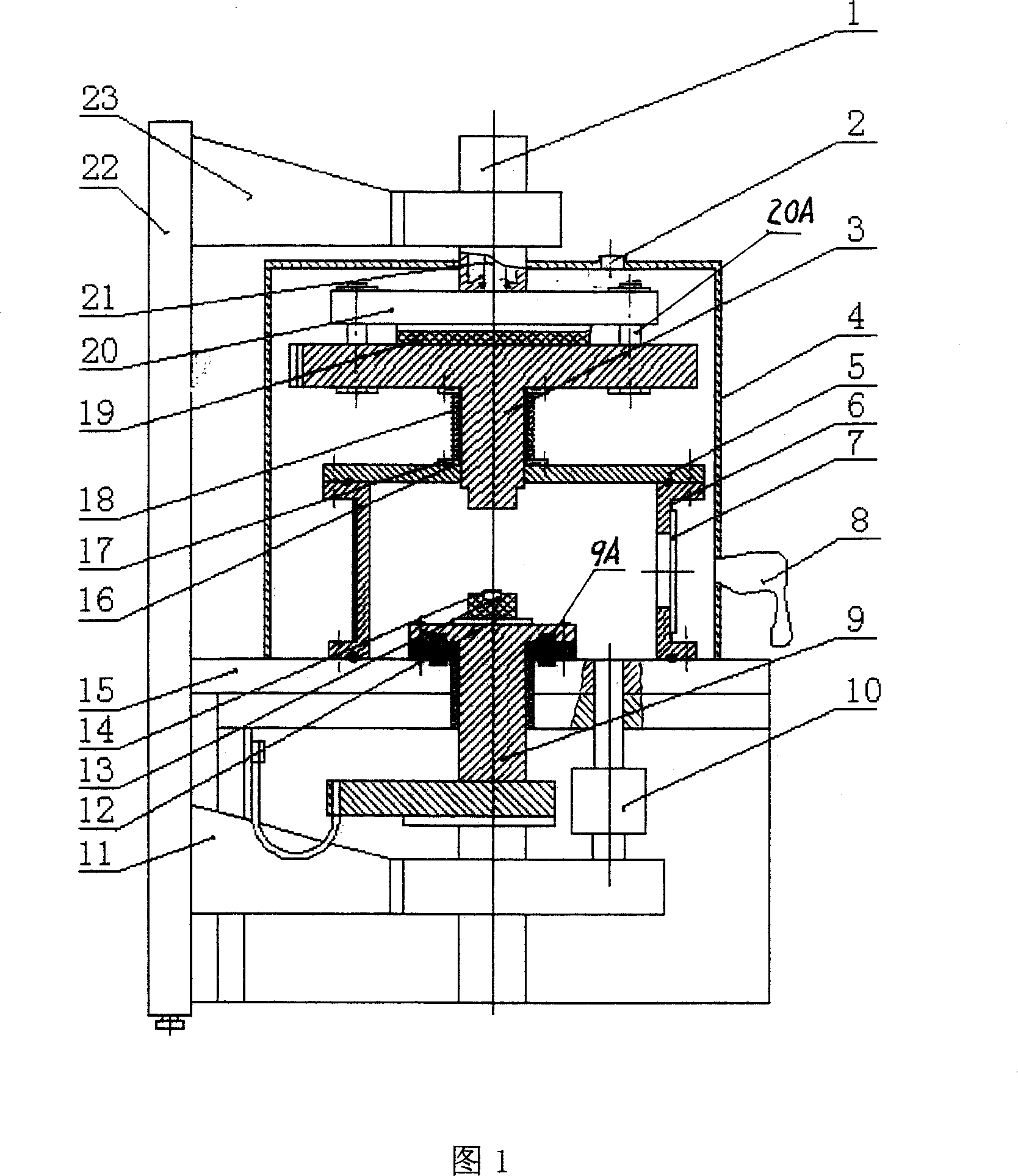
[0036] Embodiment 1. The vacuum fusion welding packaging method of the present invention comprises the following steps, as illustrated in FIG. 1:

[0037] (1), the pipe seat 14 and the pipe cap 13 to be welded are placed in the vacuum chamber 5,

[0038] (2), the vacuum chamber 5 is evacuated, and heated to degas simultaneously;

[0039] (3) The tube base 14 and the tube cap 13 located in the vacuum chamber 5 are welded and packaged together by electric welding.

Embodiment 2

[0040] Embodiment 2. Vacuum fusion welding packaging device

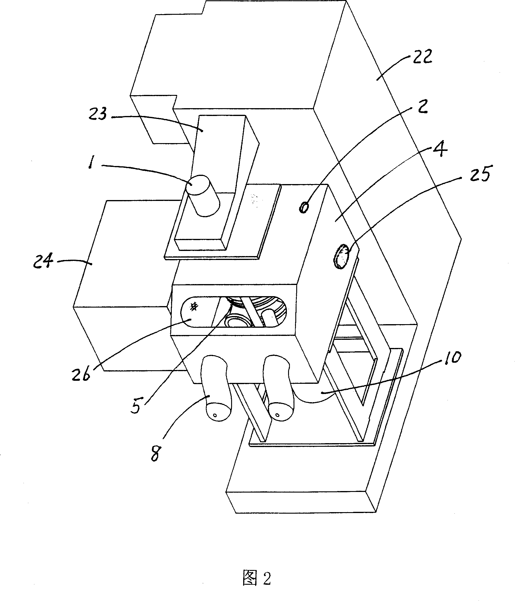
[0041] 1 and 2 are schematic diagrams of a vacuum welding packaging device, including a frame 22, a drive cylinder 1, a moving electrode 3, a static electrode 9, a nitrogen filling box 4, a vacuum chamber 5, and a vacuum pumping system 10;

[0042] The driving cylinder 1 is installed on the upper arm 23 of the frame 22; the moving electrode 3 is connected to the piston rod 21 of the driving cylinder 1; The nitrogen box 4 is surrounded by the vacuum chamber 5, and gloves 8 are installed on the nitrogen box 4; the vacuum chamber 5 has a valve 7, which communicates with the nitrogen box 4 through the valve 7, and the outer wall of the vacuum chamber 5 is wrapped with a heating jacket 6. The vacuum pumping system 10 is connected to the bottom of the vacuum chamber 5; the ends of the moving electrode 3 and the static electrode 9 extend into the vacuum chamber 5; between the moving electrode 3 and the vacuum chamber 5, a ...

Embodiment 3

[0047] Embodiment three, use a kind of operation method of this vacuum fusion welding packaging device, comprise the following steps, explain according to Fig. 1,2:

[0048] (1), preparation, the clamp 12 used during welding is cleaned before use, and the vacuum chamber 5 and the cleaned clamp 12 contained therein are preheated and degassed with the heating jacket 6;

[0049] (2), cleaning the tube base 14 and the tube cap 13 to be welded and packaged;

[0050] (3), the cleaned tube base 14 and tube cap 13 are put into a separate vacuum oven 24 (Fig. 2), and after heating and degassing, put into the vacuum chamber 5;

[0051] (4), put the tube base 14 and the cap 13 into the clamp 12 in the vacuum chamber 5 that is full of nitrogen (nitrogen is sent into by the hole 2 and the valve 7), close the valve 7, and vacuum the vacuum chamber 5 with the vacuum system 10 Vacuumize and heat with heating mantle 6;

[0052] (5) The tube base 14 and the tube cap 13 located in the vacuum cav...


PUM


Abstract

The invention relates to a vacuum welding packing method and relative packing device. Wherein, said method comprises that: (1), putting the tube base (14) and tube cap (13) in vacuum chamber (5); vacuuming the vacuum chamber (5), or heating it to remove gas; (3), powering and welding to weld the tube base (14) and tube cap (13). And in inventive device, the movable electrode (3) is connected to the piston rod (21) of driving cylinder (1); the nitrogen tank (4) is around the vacuum chamber (5); the vacuum chamber (5) via vale (7) is connected to the nitrogen tank (4); the outer wall of chamber (5) is coiled with heating sheath (6); the vacuuming system (10) is through to the vacuum chamber (5); the ends of movable electrode (3) and stable electrode (9) are inserted into chamber (5). The invention has high package degree, short welding time and high vacuum degree.

Description

technical field [0001] The invention relates to a vacuum packaging technology, in particular to a vacuum welding packaging method and a packaging device. Background technique [0002] At present, the packaging method of the tube base and tube cap of metal devices used in our country is to weld and package in the atmosphere or nitrogen environment through a combination of heating, pressurization, and static electricity, which belongs to airtight packaging. However, for the packaging of certain devices such as accelerometers or gyroscopes and MEMS (micro-electromechanical systems) devices such as radio frequency, inertial, and mechanical resonators, if it is only hermetically sealed, there will be residual gas in the device cavity such as Air or nitrogen will hinder the vibration of its vibrator, thereby affecting its sensitivity and greatly reducing the quality of the product. There is also a vacuum packaging method. The existing vacuum packaging method is a reflow soldering...

Claims


Application Information

Patent Timeline
IPC IPC(8): B23K11/00B23K11/08B23K11/36B23K11/34
Inventor 甘志银汪学方张鸿海刘胜
Owner 甘志银
Why Eureka
Try Eureka