
Light-emitting device

A technology for lighting devices and substrates, applied to electrical components, electrical solid devices, circuits, etc., can solve problems such as failure to obtain predetermined reflection efficiency, damage to optical properties, and formation of metal films, so as to improve light extraction efficiency and inhibit peeling , the effect of reducing the temperature difference

Inactive Publication Date: 2007-03-21
TOSHIBA LIGHTING & TECH CORP
View PDF1 Cites 3 Cited by
  • Summary
  • Abstract
  • Description
  • Claims
  • Application Information

AI Technical Summary

Problems solved by technology

[0005] In addition, in order to improve the reflection efficiency, a metal film is formed on the inner surface of the housing portion of the substrate, but it is difficult to uniformly form the metal film on the inner surface of the housing portion, and if the metal film deteriorates due to thermal influence or long-term use, the Unable to obtain predetermined reflection efficiency
[0006] Therefore, it is conceivable to use a reflector with high heat resistance and high reflection efficiency separately from the substrate, but if it is separated from the substrate, the heat dissipation performance will decrease, and the reflector will peel off from the substrate or warp due to thermal influence, long-term use, etc. , the optical properties are impaired

Method used


Image

  • Light-emitting device
  • Light-emitting device
  • Light-emitting device

Examples


Embodiment Construction

[0047] Hereinafter, various embodiments of the present invention will be described with reference to the drawings.

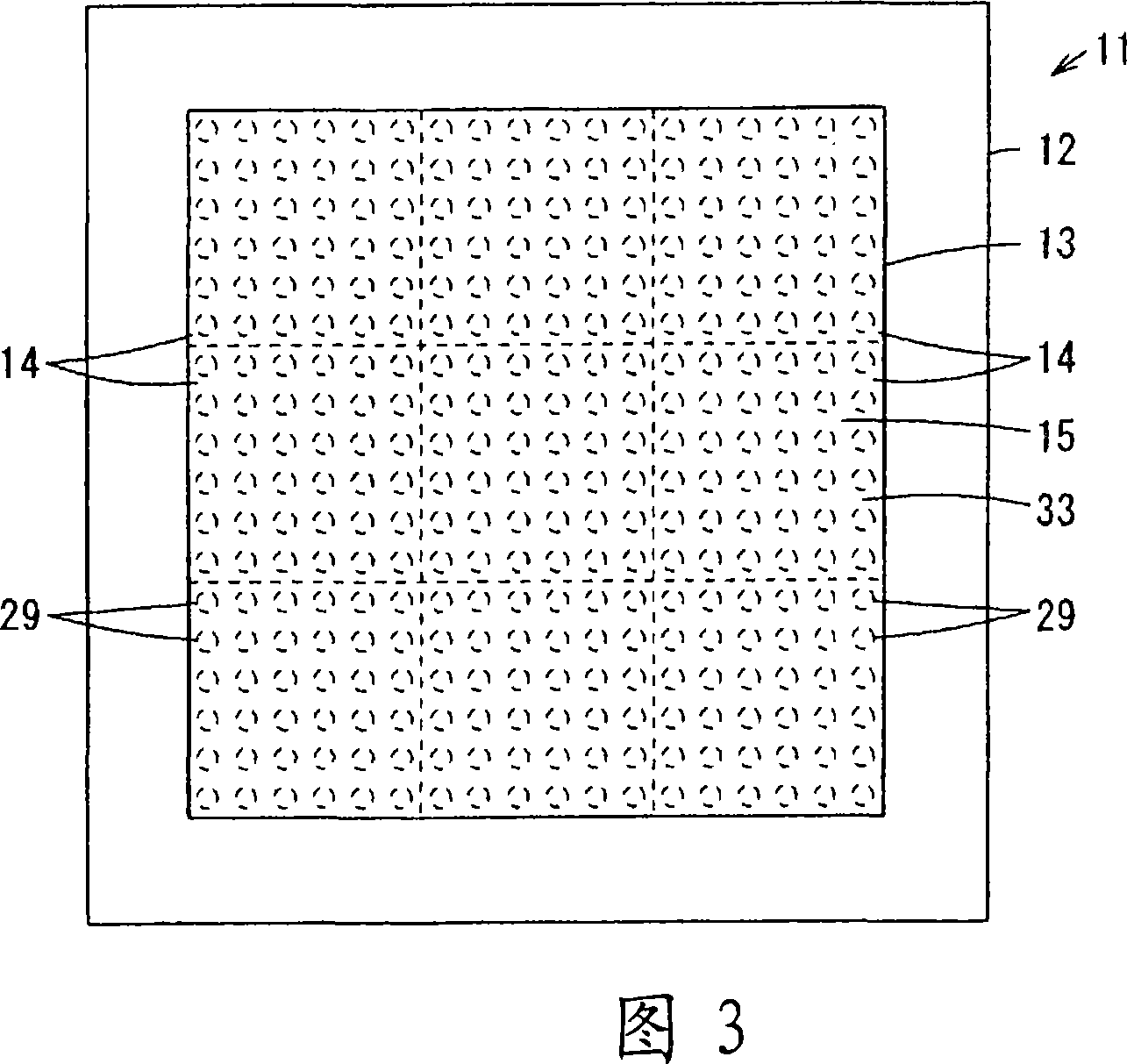
[0048] 1 to 4 show the first embodiment, FIG. 1 is a cross-sectional view of the light emitting module of the lighting device, FIG. 2 is a front view of the light emitting module, FIG. 3 is a front view of the lighting device, and FIG. 4 is a combination of materials of the light emitting module An illustration of an example.

[0049] In Fig. 3, 11 is an illuminating device, and this illuminating device 11 has the equipment main body 12 that is formed in quadrangular shape and thin shape, is formed with quadrangular opening 13 on the surface of this equipment main body 12, and the inside of this opening 13 is matrix-like. A plurality of quadrangular light-emitting modules 14 are arranged in an orderly manner, and the light-emitting surface 15 is formed by these plurality of light-emitting modules 14 .

[0050] As shown in FIG. 1 , each light-emitting module 14 ...


PUM


Abstract

A lighting system (11) enabling the suppression of peeling and warpage of a reflector (28) by increasing heat-releasing property. The reflector (28) having a storage part (29) for storing a light emitting diode element (21) is disposed on a substrate (22), a visible light converting layer (32) is formed on the storage part (29), and a lens (33) is disposed on the reflector (28). A circuit pattern (25), the light emitting diode element (21), the reflector (28), the visible light converting layer (32), and the lens (33) are disposed on the substrate (22), and the reflector (28) and the lens (33) are adhered to each other with a same type of adhesive agent (23). Thus, since the heat-releasing property of the system can be increased, the peeling and warpage of the reflector (28) can be suppressed and, accordingly, the optical characteristics of the system can be maintained.

Description

technical field [0001] The present invention relates to a lighting device using a light emitting element as a light source. Background technique [0002] Conventionally, in lighting devices using light-emitting elements such as solid-state light-emitting elements, such as light-emitting diode elements, as light sources, a plurality of recessed housing portions are formed on the surface of a substrate, and a metal film is formed on the inner surface of these housing portions. A light emitting diode element is disposed, and a transparent resin layer is filled to cover the light emitting diode element. [0003] In this lighting device, if the temperature of the light-emitting diode element becomes too high when the light-emitting diode element is turned on, the luminous efficiency of the light-emitting diode element will decrease. Therefore, a metal substrate or a composite substrate containing epoxy resin and alumina is used as the substrate. Efficiently dissipate heat, or se...

Claims


Application Information

Patent Timeline
Patent Type & Authority Applications(China)
IPC IPC(8): H01L33/00H01L33/58
CPCH01L2224/16225H01L2224/48091H01L2224/73265H01L2224/8592H01L2924/181
Inventor 森山严与中西晶子岩本正己野木新治小川光三清水惠一齐藤明子川岛净子三瓶友广户田雅宏
Owner TOSHIBA LIGHTING & TECH CORP
Learn More