Liquid-jet head and liquid-jet apparatus, and methods for manufacturing the same
A technology of a droplet ejection head and a manufacturing method, applied in directions such as printing, can solve the problems such as the inability to ensure the gas sealing for substrate cooling and the limit of production capacity, and achieve the effects of increasing density, reducing flow channel resistance, and reducing deviation
- Summary
- Abstract
- Description
- Claims
- Application Information
AI Technical Summary
Problems solved by technology
Method used
Image

Examples
Embodiment 1
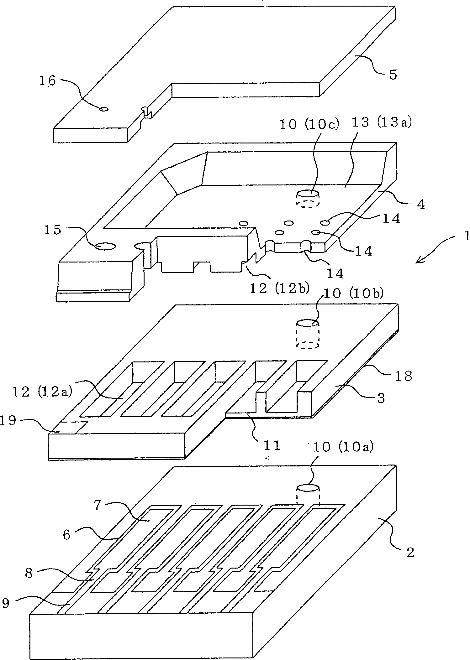
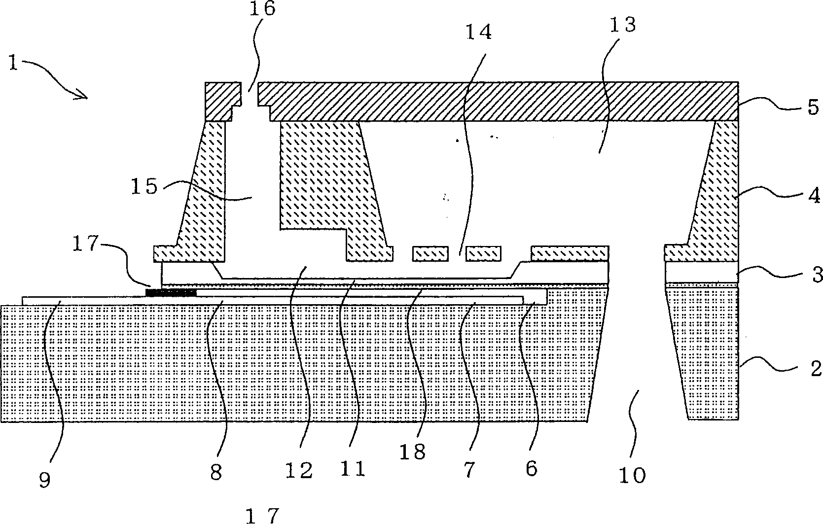
[0064] figure 1 It is an exploded view showing the droplet discharge head according to Embodiment 1 of the present invention. also, figure 2 is a cross-sectional view of the droplet ejection head. figure 1 and figure 2 Represents a part of the droplet ejection head (It should be noted that the components shown in the figure include figure 1 , figure 2 , in each of the following drawings, the dimensional relationship of each constituent member may be different from the actual one. In addition, the top of the figure is up, and the bottom is down, for explanation).
[0065] like figure 1 As shown, four substrates including the electrode substrate 2 , the chamber substrate 3 , the memory substrate 4 , and the nozzle substrate 5 are stacked in order from the bottom to constitute the droplet ejection head of this embodiment. Here, the electrode substrate 2 and the cavity substrate 3 are bonded by anodic bonding. In addition, the cavity substrate 3 and the memory substrate...
Embodiment 2
[0089] Figure 7 and Figure 8 It is a diagram showing the manufacturing steps of the memory substrate 4 of the droplet discharge head according to the second embodiment of the present invention. according to Figure 7 and Figure 8 , the method of manufacturing the memory substrate 4 of the second embodiment will be described.
[0090] Figure 9 It is a figure which shows the outline|summary of a non-contact exposure apparatus. Here, it is an exposure apparatus (sequential movement exposure apparatus) 80 capable of reduced exposure. exist Figure 9In the exposure device 80, the light emitted from the light source 81 is reflected by the mirror part 82, then condensed by the condensing lens part 83, and passes through the exposure mask 84 (reticle) for patterning the resist mask 72. 84, incident to the optical system component 85. The optical system part 85 has a condensing lens (not shown) for reducing, and reduces the patterned shape based on the exposure mask 84 by a...
Embodiment 3
[0098] Figure 10 It is a diagram showing the manufacturing steps of the memory substrate 4 of the droplet ejection head according to the third embodiment of the present invention. according to Figure 10 A method of manufacturing the memory substrate 4 will be described. Here, in this embodiment, also perform Figure 7 Steps from (a) to (e). In these steps, the same processing as that described in the second embodiment is performed, so the description is omitted.
[0099] Etching mask 91 made of silicon oxide deposited on the entire surface is formed by thermal oxidation. Resist patterning is then performed, and etching is performed with a hydrofluoric acid solution or the like to remove the etching mask 91 with respect to the portions corresponding to the nozzle communication holes 15 and the storage recesses 13a. Here, the portion corresponding to the nozzle communication hole 15 is removed so that the silicon substrate 71 is exposed to the C surface side and the N sur...
PUM
 Abstract
Description
Claims
Application Information
 - R&D
- Intellectual Property
- Life Sciences
- Materials
- Tech Scout
- Unparalleled Data Quality
- Higher Quality Content
- 60% Fewer Hallucinations
Browse by: Latest US Patents, China's latest patents, Technical Efficacy Thesaurus, Application Domain, Technology Topic, Popular Technical Reports.
© 2025 PatSnap. All rights reserved.Legal|Privacy policy|Modern Slavery Act Transparency Statement|Sitemap|About US| Contact US: help@patsnap.com