Method for fabricating quartz base plate of optical device

A technology of quartz substrate and manufacturing method, which is applied in the direction of manufacturing tools, glass manufacturing equipment, glass molding, etc., can solve the problems of damage to workers' skin and respiratory tract, difficult precision of quartz substrate, low production speed and other problems, and achieve labor-saving economy Efficiency and ease of operation, elimination of local surface hidden cracks, and elimination of jig positioning errors

Active Publication Date: 2011-08-17
深圳市天阳谷科技发展有限公司
View PDF1 Cites 0 Cited by
  • Summary
  • Abstract
  • Description
  • Claims
  • Application Information

AI Technical Summary

Problems solved by technology

[0005] B. Since it is necessary to use special fixtures to debug and position on the machine tool, and to fix the quartz rods one by one on the special fixture, and then grind the quartz rods one by one, in addition to the above-mentioned uneconomical defects, the production efficiency There are low-efficiency defects that cannot increase the production speed, and there are still defects that are not suitable for mass production
[0006] C. Since the quartz rod is fixed in the special jig groove with wax, after the melted wax is taken out, the surface of the quartz rod must be covered with wax, and the wax must be soaked in solvents such as thinner or acetone before it can be completely removed , and solvents such as thinner or acetone soak the wax, whether the residual solution is poured out or recycled again, the damage to the health of production personnel and the environment is obvious, such as damage to the skin and respiratory tract of workers, waste liquid Pollution of groundwater and air, etc.
[0007] D. Due to the series of operations such as material selection, jig positioning, waxing fixation, grinding and cutting, wax melting and pick-up, the quartz substrate is due to material size errors, jig positioning errors, and quartz rod movement during waxing Error, machine tool error, grinding and cutting error, diamond grinding wheel wear error and other factors lead to the difficulty of controlling the precision of the produced quartz substrate, and the deformation and offset of the optical fiber positioning groove of the quartz substrate. Therefore, this manufacturing method has poor production stability and poor product quality. High, low pass rate
[0008] E. Because this kind of quartz substrate is made by mechanical grinding, the surface of the optical fiber positioning groove is extremely rough and the micro cracks are serious. The partial surface of the optical fiber positioning groove has formed hidden cracks, which are easy to crack and break when dispensing glue to fix the optical fiber. Resulting in a low qualified rate of dispensing and an increase in product cost

Method used


Image

  • Method for fabricating quartz base plate of optical device
  • Method for fabricating quartz base plate of optical device
  • Method for fabricating quartz base plate of optical device

Examples


Embodiment Construction

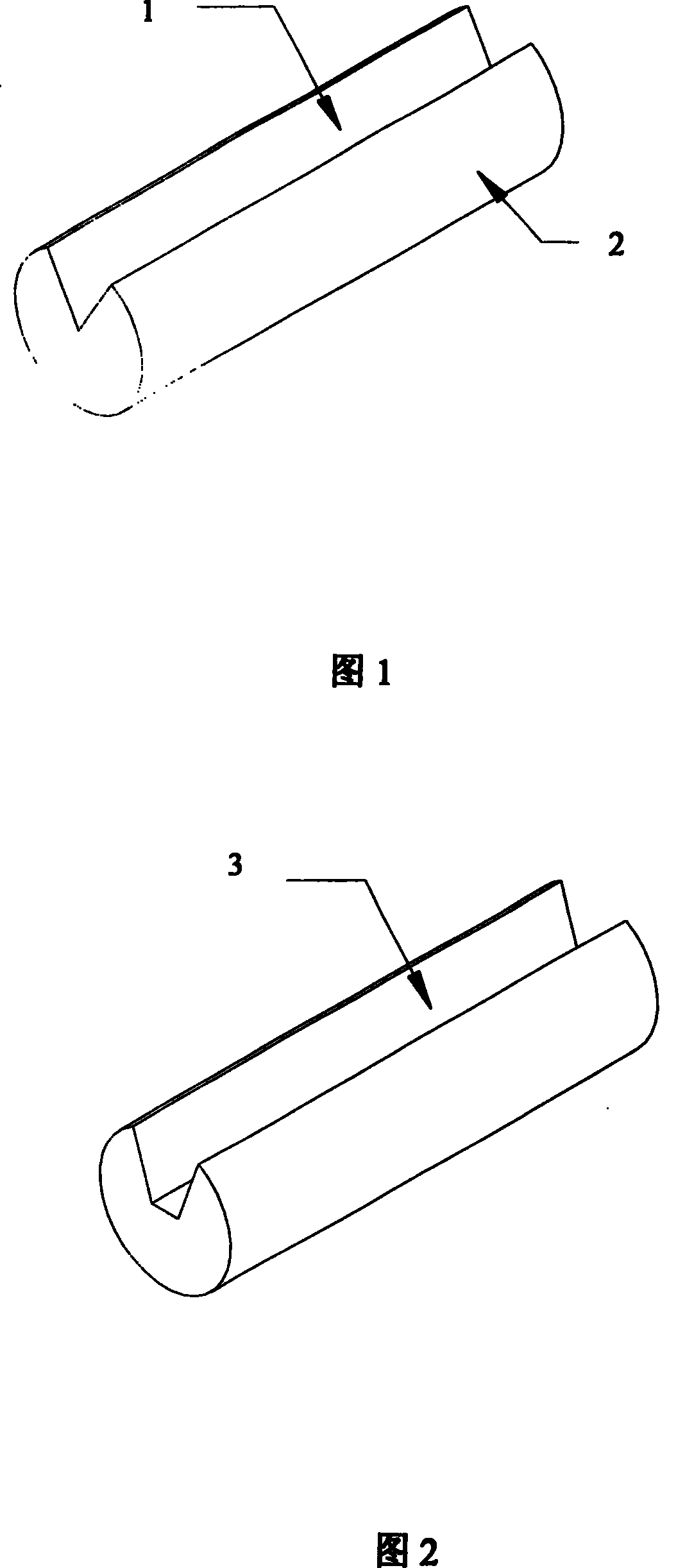
[0032] figure 1 It is a three-dimensional schematic diagram of a quartz substrate processed by general machinery, 1 is the optical fiber positioning groove, and 2 is the quartz rod. This kind of quartz substrate has undergone a series of processes such as material selection, jig positioning, waxing and fixing, grinding and cutting, and wax melting. The quartz substrate produced by the engineering operation, due to the size error of the material, the positioning error of the fixture, the movement error of the quartz rod when pouring wax, the error of the machine tool, the error of grinding and cutting, the wear error of the diamond grinding wheel and other factors, the accuracy of the produced quartz substrate is It is not easy to control, and the optical fiber positioning groove of the quartz substrate is deformed and offset. Therefore, this manufacturing method has poor production stability, low product quality, and low pass rate.

[0033] Fig. 2 is a three-dimensional schema...


PUM


Abstract

This invention relates to a method for manufacturing quartz substrate for optical devices. The method comprises: (1) washing quartz rod or quartz tube, and fixing in a high temperature graphite oven; (2) introducing inert gas into the high temperature graphite oven; (3) pulling, wire-drawing and cutting the quartz rod or quartz tube to obtain quartz substrate. The method has such advantages as low cost, mass production, and high product quality.

Description

technical field [0001] The invention relates to a method for manufacturing a quartz substrate of an optical device (such as an optical coupler, a ribbon-shaped optical fiber fusion splicing protector, etc., the same below), in particular to a method for manufacturing a quartz substrate for producing an optical device by high-temperature melting wire drawing. Background technique [0002] At present, the manufacturing method of the quartz substrate used to fix the optical fiber in the optical device is mainly through a series of engineering operations such as material selection, jig positioning, wax fixing, grinding and cutting, and wax melting. On a quartz rod of a predetermined size, Using mechanical processing to produce optical fiber positioning grooves with a certain shape of "V" or "U" or other shapes, please refer to the patent No. ZL01104268.0 issued by the Patent Office of the State Intellectual Property Office on June 16, 2004. Patent. [0003] It is undeniable tha...

Claims


Application Information

Patent Timeline
Patent Type & Authority Patents(China)
IPC IPC(8): C03B23/037
Inventor 黄燕平王浪刚李立周小平
Owner 深圳市天阳谷科技发展有限公司
Why Eureka
Try Eureka