
Full coated high pentration type brightening optical module suitable for liquid crystal display

A technology of liquid crystal display and optical components, which is applied in the field of high-transmittance brightening optical components, which can solve the problems of not having the function of light polarization state conversion and light recovery mechanism to enhance brightness, and achieve the reduction of resources required for production and cost reduction , The effect of saving material cost

Active Publication Date: 2006-11-08
IND TECH RES INST
View PDF5 Cites 11 Cited by
  • Summary
  • Abstract
  • Description
  • Claims
  • Application Information

AI Technical Summary

Problems solved by technology

In terms of the preparation of polarizers, U.S. Patent 6,049,428 discloses a technology to complete a new type of E-type polarizer by coating disc columnar polymer molecules (supermolecular). The penetration axis is parallel to the molecular optical axis and the traditional vertical molecular optical axis. The O-type polarizer of the axis is different, but basically it is still a light-absorbing polarizing film, which does not have the functions of light polarization state conversion, light recycling mechanism and resulting brightness enhancement

Method used


Image

  • Full coated high pentration type brightening optical module suitable for liquid crystal display
  • Full coated high pentration type brightening optical module suitable for liquid crystal display

Examples


Embodiment 1

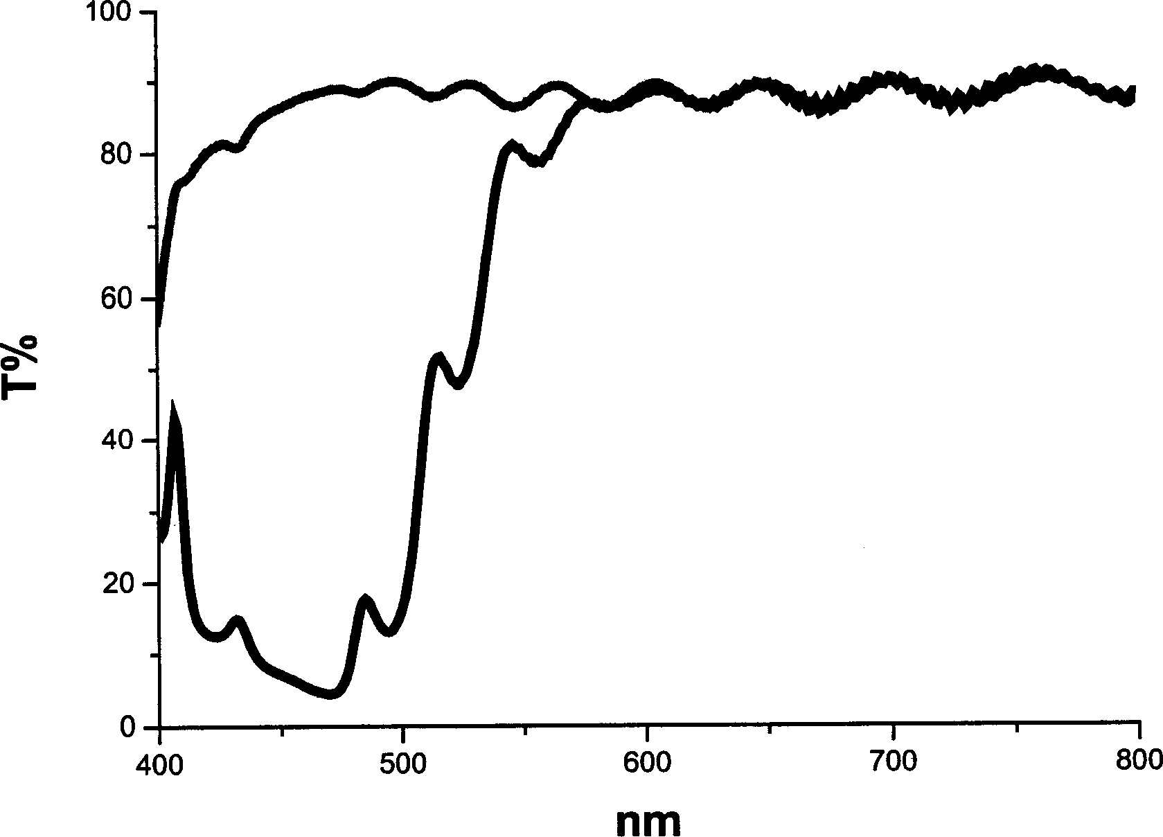
[0018] Polymerizable cholesteric liquid crystals SLM 90032 and SLM 90034 were formulated into a 25wt% solution with SLM 90032:SLM 90034=70:30 ratio and toluene (Toluene), and at the same time, 1wt% of UV light-enabling agent Irgacure 907(R) (Ciba Geigy) was added , and then coated on the aligned PET film with a thickness of 50 μm, dried at 80°C for 2 minutes, and then used 100W / cm 2 After 20 seconds of irradiation with a special UV lamp, a film is formed, and finally a cholesteric phase liquid crystal film with a film thickness of about 5 μm is obtained.

[0019] The polymerizable liquid crystal SLM 90519 and toluene (Toluene) were formulated into a 10wt% solution, and 1wt% of UV light initiator Irgacure 907(R) was added at the same time. Apply this solution on the above-mentioned cholesteric liquid crystal film, dry it at 80°C for 1 minute, and use 100W / cm 2 A film with a thickness of 2 μm is formed after being irradiated with a UV lamp for 20 seconds, thus completing the pa...

Embodiment 2

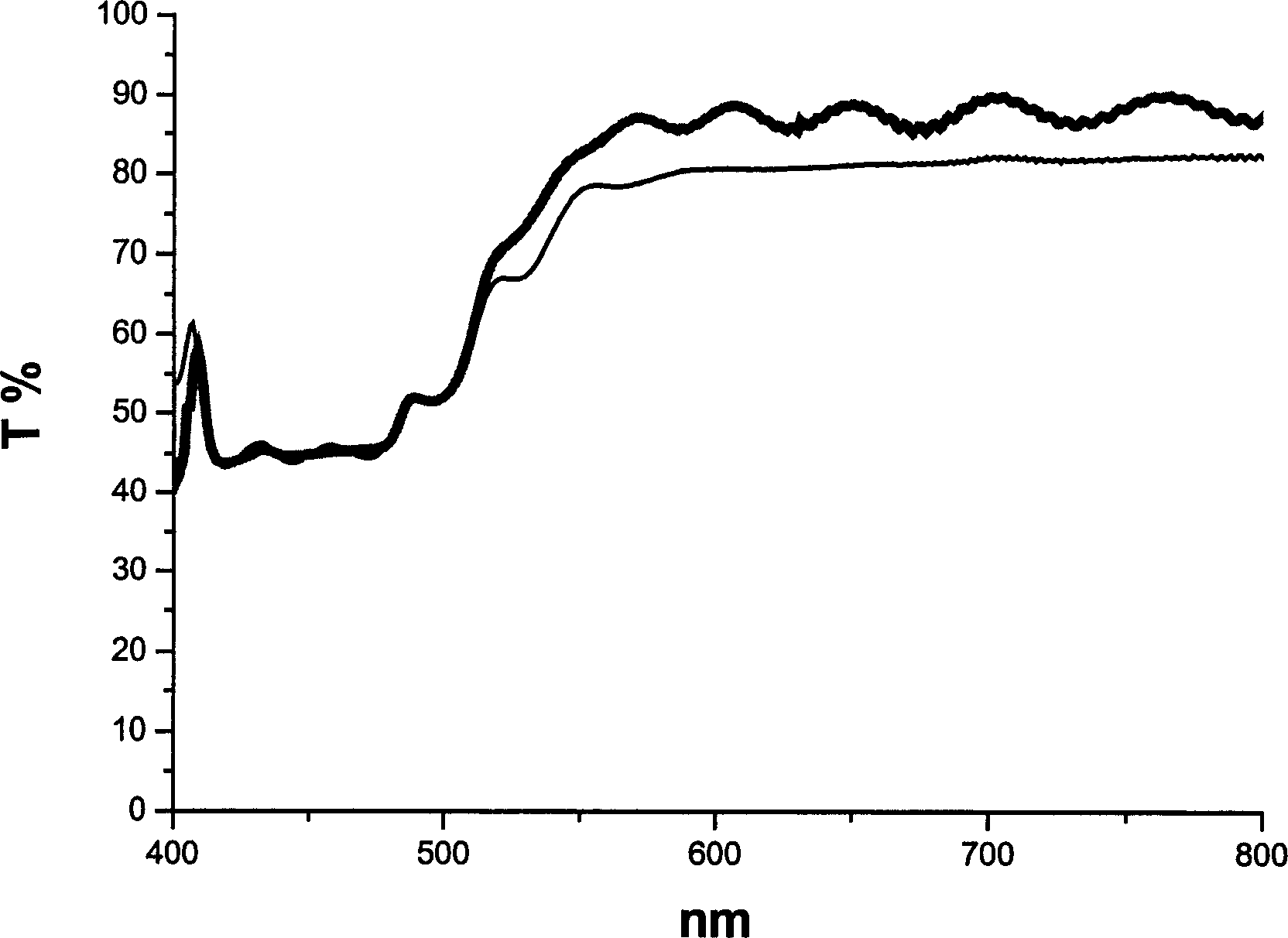
[0024] A brightness-enhancing optical assembly integrated with a polarizing film was prepared by using the brightness-enhancing optical assembly prepared in Example 1. First confirm the optical axis direction of the above-mentioned 1 / 4 wavelength retarder, and apply the following solution in the direction of its optical axis at an angle of 45 degrees: make a 20wt% solution of polymerizable liquid crystal SLM 90519 and toluene (Toluene), and add 1 wt% UV light initiator Irgacure 907(R) and 3 wt% black dichroic dye. After drying at 80°C for 2 minutes, use 100W / cm 2 A film with a thickness of 2 μm is formed after being irradiated with a UV lamp for 1 minute, which is the part of the polarizer in the brightness-enhancing optical component.

[0025] The brightness-enhancing optical component manufactured in the above-mentioned way has a thickness of only about 59 μm, and it has the characteristics of brightness enhancement and high penetration when placed on a backlight LCD.


PUM

PropertyMeasurementUnit
thicknessaaaaaaaaaa
thicknessaaaaaaaaaa
thicknessaaaaaaaaaa

Abstract

This invention discloses a high penetration light-increasing optical component including forming a LC film of the cholesterin phase and an 1 / 4 wavelength delay film on a matrix orderly and further including forming a polarized film on the delay film, in which, the first two films are formed by coating and the polarized film is formed by coating or adhering a pre-formed polarized film on the delay film. This invention with the polarized film combines the high penetration light increasing optical component with the backlight module of the LED with the polarized film as the brightness increased polarized light source of a LED.

Description

technical field [0001] The invention is mainly applied to a high-transmission brightness-increasing optical component of a backlight LCD, in particular to a high-transmission brightness-enhancing optical component integrated with a polarizing film on a backlight LCD. Background technique [0002] Among all flat panel displays, liquid crystal displays are the only ones that use linearly polarized light to create bright, dark, and gray scales. First of all, the light from the backlight module is processed by the polarizer assembly to produce linearly polarized light; as the liquid crystal molecules are arranged and twisted, bright and dark changes occur, which enriches the display content. [0003] However, the total brightness of the current liquid crystal display is only 4-6% of that provided by its backlight source, and the dichroic polarizer assembly that absorbs half of the incident light is one of the main reasons for the loss. Therefore, if the incident light can be pr...

Claims


Application Information

Patent Timeline
Patent Type & Authority Applications(China)
IPC IPC(8): G02F1/137G02B5/30G02F1/133
Inventor 吴昱勋谢葆如郭惠隆
Owner IND TECH RES INST
Learn More