Image pick-up device and image pick-up method
A technology for a camera device and a subject to be photographed, which is applied in the directions of measuring devices, focusing devices, static cameras, etc.
- Summary
- Abstract
- Description
- Claims
- Application Information
AI Technical Summary
Problems solved by technology
Method used
Image
Examples
Embodiment 1
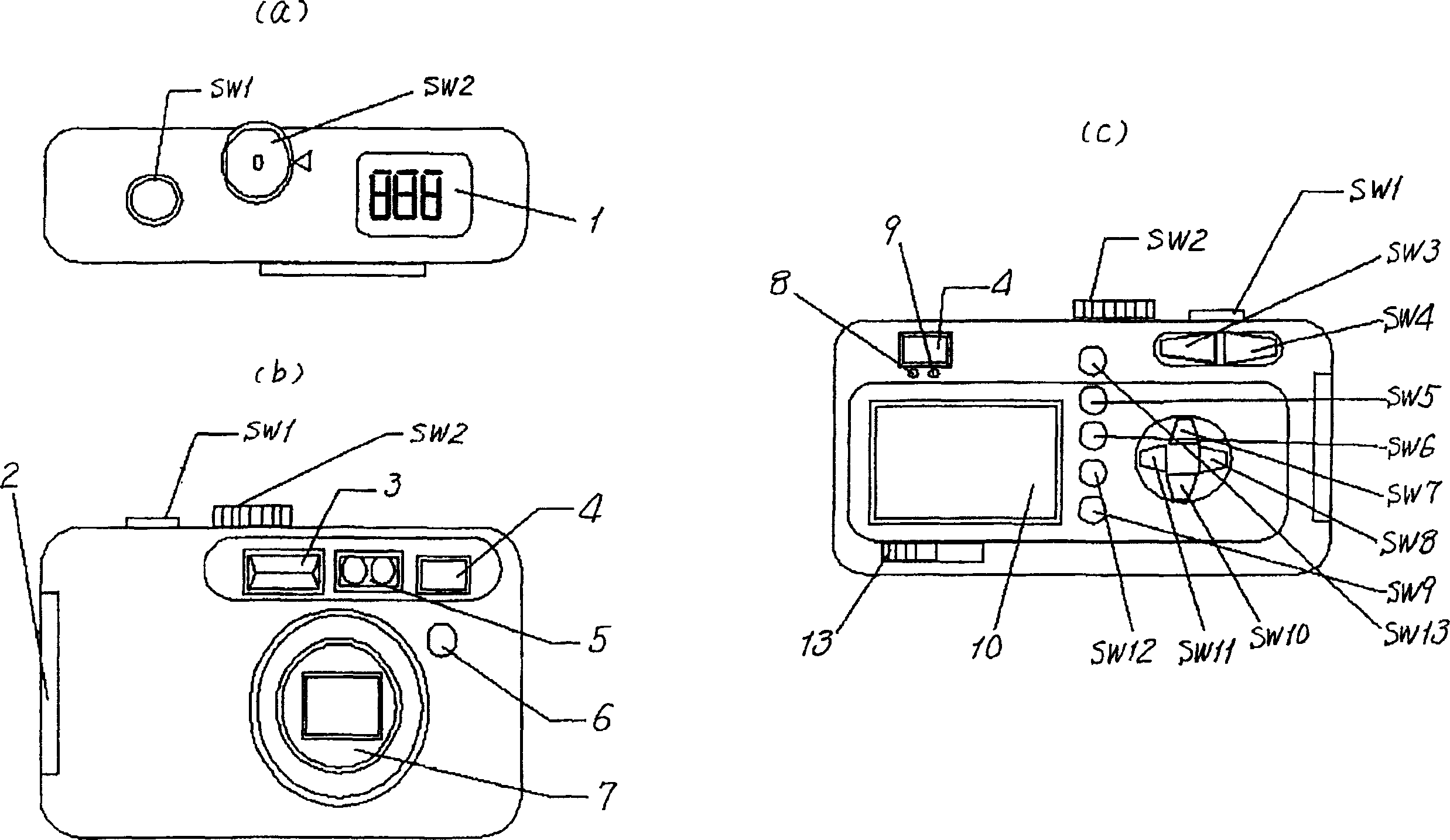
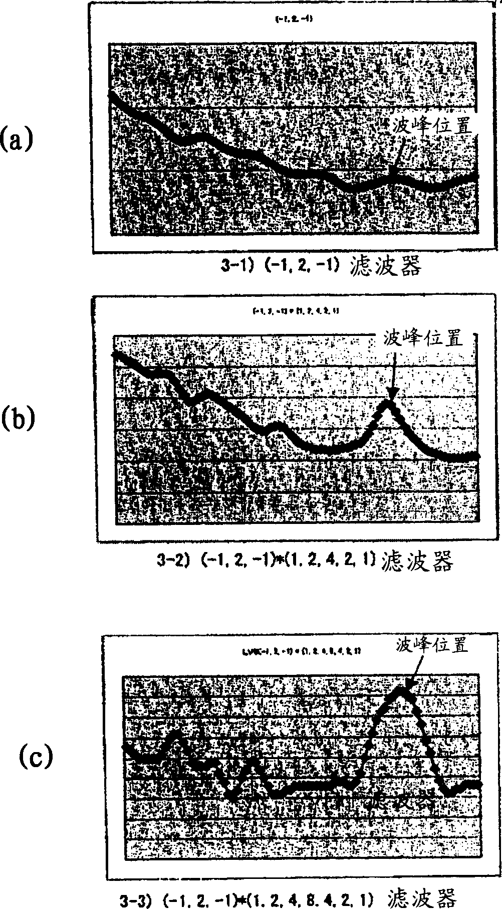
[0056] Figure 4 The operation of the imaging device of the first embodiment is shown. First, by operating figure 1 The shown releaser shutter button SW1 starts to operate, and the brightness of the subject is determined based on the photometry result immediately before the releaser shutter button was pressed (4-2). Subject brightness can be measured from the output of CCD101. A process of selecting a frequency component extraction filter based on the luminance (LV value) obtained from the photometry result (4-3) is performed. In this example, prepare as Figure 7 The three filters shown, for example, by following the Figure 6 The process shown in the flowchart to select the frequency extraction filter. Concrete representation Figure 7 The structures of the three filters shown are as follows. The first filter is a composite filter of a high-pass filter composed of coefficients '-1', '2', '-1' and a low-pass filter composed of coefficients '1', '2', '1'. The second fi...
Embodiment 2
[0065] Next, with Figure 5 The shown flowchart is centered, and Example 2 is demonstrated, referring to it.
[0066] figure 1 When the shown releaser shutter button SW1 is operated, the brightness of the subject is determined based on the photometry result immediately before the releaser shutter button was pressed (5-2). A process of selecting a frequency component extraction filter based on the luminance (LV value) obtained from the photometry result (5-3) is performed. In this example, prepare as Figure 7 of the three filters shown, by e.g. Figure 8 Shown in the flowchart is such processing to select the frequency extraction filter. The filter selection process first judges whether the brightness of the subject is less than LV6 (10-1), and if it is not less than LV6, that is, greater than or equal to LV6, it is judged whether it was not selected during the last scan (10-2), if If there is no selection, then select the first filter (10-3), if it was selected during th...
Embodiment 3
[0072] Next, with Figure 9 The shown flowchart focuses on Embodiment 3. operate figure 1 When the releaser shutter button SW1 is shown, the brightness of the subject is determined based on the photometry result immediately before the releaser button was pressed (11-2). Next, the focus lens is moved to the focus start position (11-3), and pixel data is acquired (11-4). This pixel data is a digital RGB signal taken into the CCD I / F block of the digital signal processing IC. After the acquisition of the pixel data, it is judged whether or not scanning has been completed to the end of the focus position (11-5). If the end point of the focus position is not completed, the focus position is moved sequentially (11-6), the end point is scanned, and the same process is performed until the end (11-5).
[0073] Next, a frequency component extraction filter is selected based on the luminance (LV value) obtained from the photometry result (11-7). In this example, prepare as Figure ...
PUM
 Abstract
Description
Claims
Application Information
 - R&D
- Intellectual Property
- Life Sciences
- Materials
- Tech Scout
- Unparalleled Data Quality
- Higher Quality Content
- 60% Fewer Hallucinations
Browse by: Latest US Patents, China's latest patents, Technical Efficacy Thesaurus, Application Domain, Technology Topic, Popular Technical Reports.
© 2025 PatSnap. All rights reserved.Legal|Privacy policy|Modern Slavery Act Transparency Statement|Sitemap|About US| Contact US: help@patsnap.com


