
Surface processing and forming method of photoresist layer

A photoresist layer and photoresist technology are applied in the field of surface treatment of photoresist layers to form patterned photoresist layers, which can solve the problem of film layer pattern distortion and resolution reduction , contour distortion and other problems to avoid deformation

Active Publication Date: 2010-11-17
UNITED MICROELECTRONICS CORP
View PDF2 Cites 0 Cited by
  • Summary
  • Abstract
  • Description
  • Claims
  • Application Information

AI Technical Summary

Problems solved by technology

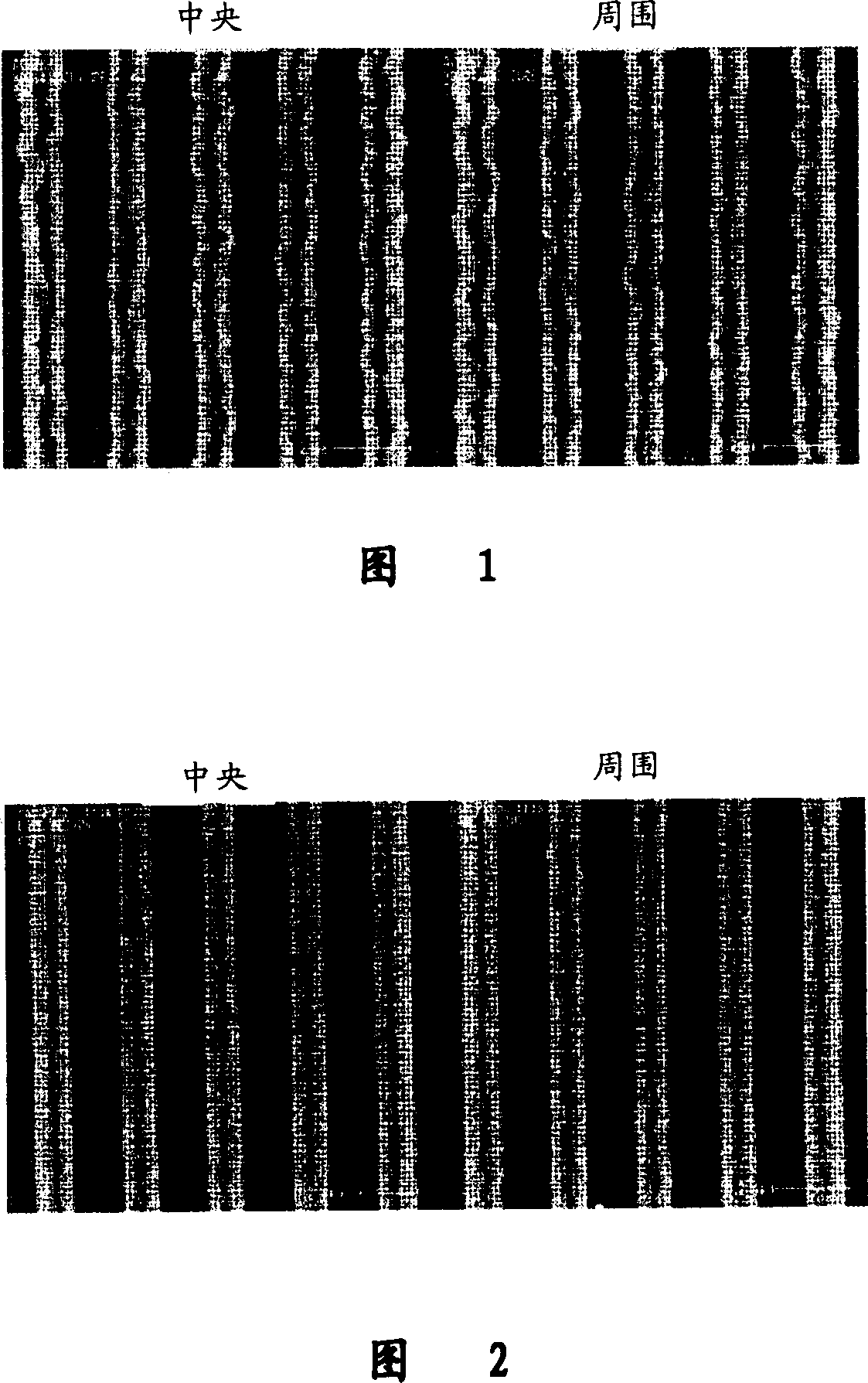
Depend on figure 1 It can be seen that the profile of the patterned photoresist layer is distorted due to the relatively narrow width, so that when the photoresist layer is used as a mask to perform the etching process, the film to be etched Layers produce pattern distortion or issues that result in reduced resolution

Method used


Image

  • Surface processing and forming method of photoresist layer
  • Surface processing and forming method of photoresist layer
  • Surface processing and forming method of photoresist layer

Examples


Embodiment Construction

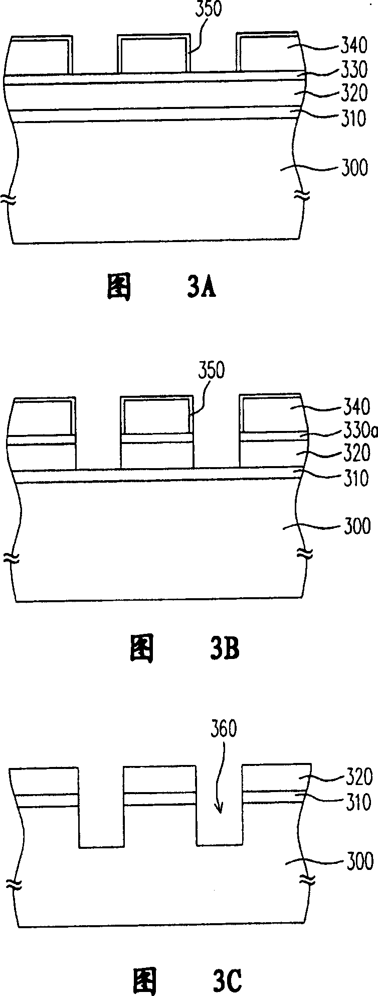
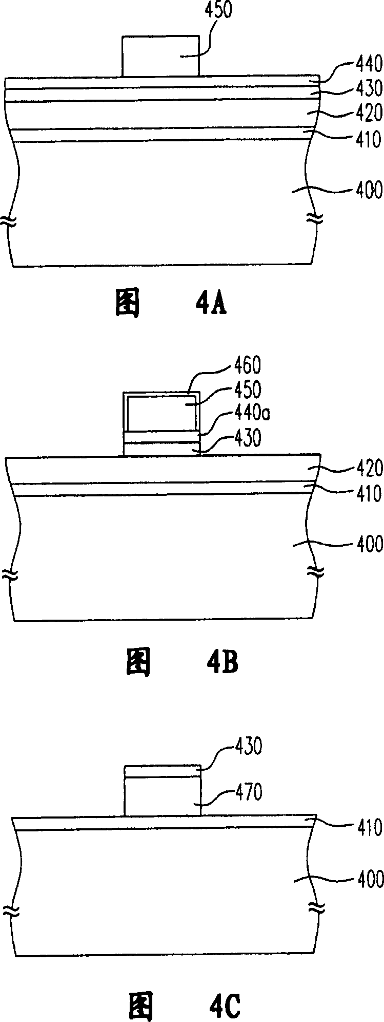
[0029] Since the patterned photoresist layer obtained by the photolithography process tends to be deformed or collapsed when the line width becomes larger and larger, the present invention proposes a surface of the photoresist layer approach to deal with the above problems. The surface treatment method of this photoresist layer is to use photolithographic equipment to form a patterned photoresist layer on the wafer, and then move the wafer to the etching reaction, using at least hydrogen bromide or iodine A reaction gas of hydrogen hydride is used to perform a surface treatment step on the photoresist layer to form a hardened layer on the surface of the photoresist layer.

[0030] The above surface treatment step uses radio frequency voltage to excite the reactive gas into plasma to form a hardened layer on the surface of the photoresist layer, and the hardened layer can effectively maintain the profile of the patterned photoresist layer. In addition, the material of the abov...


PUM


Abstract

A surface processing method of photo resist layer utilizes reaction gas containing hydrogen bromide or hydrogen iodide to carry out a surface treatment on photo resist layer after patternized photo resist layer is formed on chip in order to prepare a hardened layer on surface of photo resist layer .The said surface treatment process is carried out simultaneously with etching process.

Description

technical field [0001] The invention relates to a semiconductor manufacturing process, in particular to a surface treatment method of a photoresist layer and a method for forming a patterned photoresist layer using the aforementioned surface treatment method. Background technique [0002] In the case of higher and higher circuit integration requirements, the design of the size of the entire circuit element is also forced to advance in the direction of continuous reduction in size. At present, the semiconductor process has entered the 90-nanometer process. The most important step in the entire semiconductor process is the photolithography process. The decision of any critical dimension is dominated by the photolithography step. [0003] However, in the photolithography process, the patterned photoresist layer is formed by exposing and developing the photoresist layer. The relatively narrow width of the photoresist layer makes it difficult to maintain the profile of the photo...

Claims


Application Information

Patent Timeline
Patent Type & Authority Patents(China)
IPC IPC(8): G03F7/26
Inventor 黄国书
Owner UNITED MICROELECTRONICS CORP
Learn More