
Ion source apparatus and method

An ion source, plasma technology, applied in the field of cyclotron design, can solve the problems of performance degradation, strict manufacturing tolerance, short life of ion source pipeline 200, etc.

Inactive Publication Date: 2006-08-09
GENERAL ELECTRIC CO
View PDF0 Cites 33 Cited by
  • Summary
  • Abstract
  • Description
  • Claims
  • Application Information

AI Technical Summary

Problems solved by technology

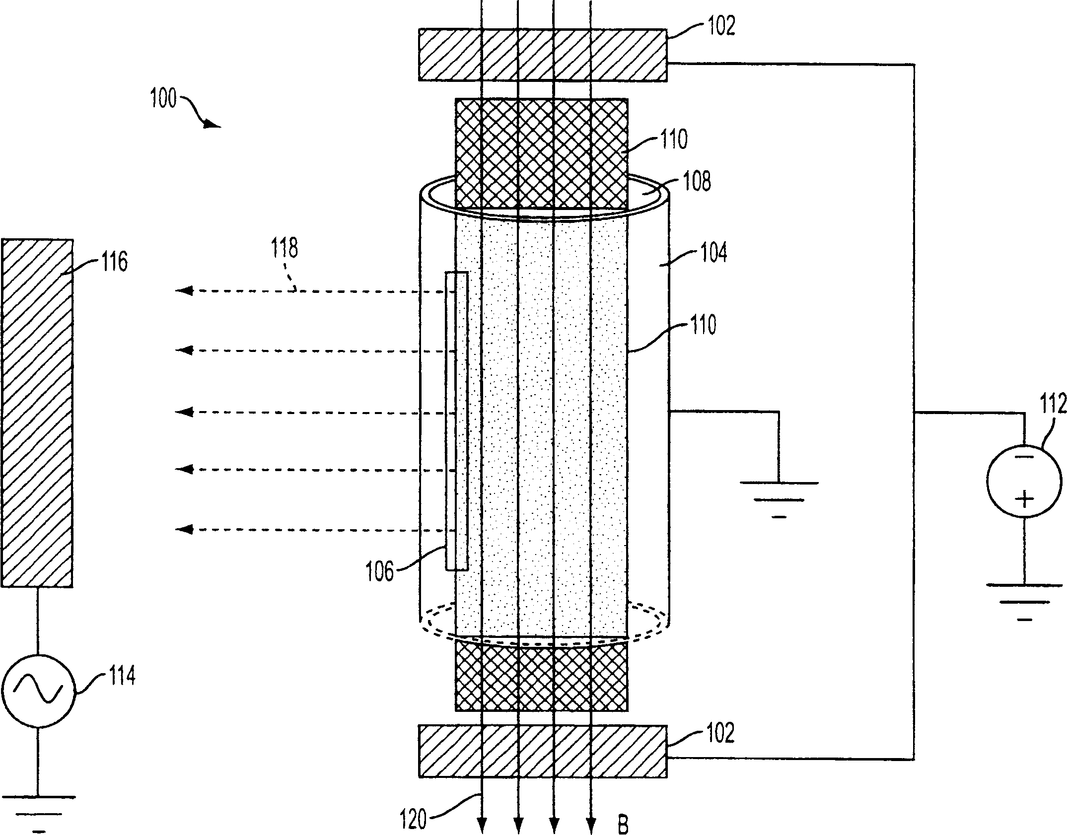
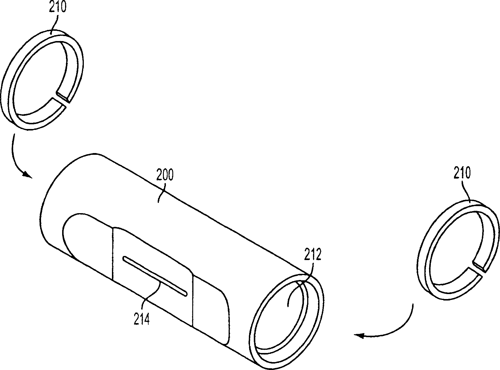
For example, the use of the confinement ring 210 may require some amount of time for assembly and adjustment during the manufacturing process
and prior art designs of confinement rings can impose tight manufacturing tolerances
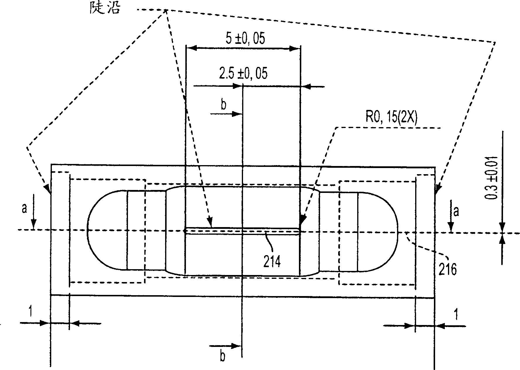
In addition, the slit opening 214 can degrade relatively quickly due to bombardment by ions generated in the plasma column 218, resulting in a short lifetime of the ion source tubing 200

Method used


Image

  • Ion source apparatus and method
  • Ion source apparatus and method
  • Ion source apparatus and method

Examples


Embodiment Construction

[0018] Typical embodiments of the present invention will be described in detail below.

[0019] see Figure 8 , shows a perspective view of a typical ion source conduit 300 according to one embodiment of the present invention. Ion source tubing 300 can be used for similar figure 1 The ion source shown is that of a plasma-based ion source. A plasma discharge (not shown) may be maintained in or near ion source conduit 300 . Ion source tubing 300 may be made of heat and plasma discharge resistant metals such as copper and tungsten. As shown, a typical ion source conduit 300 generally has a cylindrical shape. In the front side of the ion source conduit 300 there may be a slit opening 310 for extracting ions. There may be end openings 314 in the ends of the ion source conduit 300 to accommodate the flow of gas components and help define the shape and location of the plasma discharge. Inside the ion source conduit 300, there may be a pre-shaped cavity 312 that further defines ...


PUM


Abstract

The present invention relates to a method and apparatus for improving the lifetime and performance of ion sources in cyclotrons. According to one embodiment, the invention includes an ion source conduit (300) for maintaining a plasma discharge therein. The ion source conduit (300) includes a slit opening (310) along a side of the ion source conduit (300), wherein the slit opening (310) has a width less than 0.29 mm. The ion source conduit (300) also includes an end opening (314) in an end of the ion source conduit (300). The end opening (314) is smaller than the inner diameter of the ion source conduit (300) and moves 0-1.5 mm from the central axis (316) of the ion source conduit (300) towards the slit opening (310). The plasma column moves 0.2 to 0.5 mm relative to the slit opening (310). The ion source conduit (300) includes a cavity (312) adapted for the plasma discharge. The invention also relates to a method for manufacturing an ion source conduit (300).

Description

technical field [0001] The present invention relates generally to the field of cyclotron design for radiopharmaceuticals, and more particularly to methods and apparatus that enable improved ion source lifetime and performance. Background technique [0002] Hospitals and other health care providers rely extensively on positron emission tomography (PET) for diagnostic purposes. Positron emission tomography scanners produce images that reveal a variety of biological processes and functions. In a PET scan, the patient is initially injected with a radioactive substance known as a PET isotope (or radiopharmaceutical). For example, positron emission tomography isotopes can be 18 F-fluoro-2-deoxyglucose (FDG), a sugar that includes radioactive fluorine. PET isotopes are involved in certain bodily processes and functions, and their radioactive nature enables PET scanners to produce images showing those functions and processes. For example, when injecting 18 F-fluoro-2-deoxygluco...

Claims


Application Information

Patent Timeline
Patent Type & Authority Applications(China)
IPC IPC(8): H05H13/00H05H1/24H05G2/00G21G1/10
CPCH05H13/00H01J27/08
Inventor J·O·诺尔林J·-O·贝里斯特伦
Owner GENERAL ELECTRIC CO
Learn More