
Back washing shell and tube type heat exchanger with sliding cleanliness unit built in

A technology of shell-and-tube heat exchangers and shell-and-tube heat exchangers, which is applied in the field of backwashing shell-and-tube heat exchangers with built-in sliding cleaners, and can solve the problems of increasing equipment investment, increasing system and equipment resistance, and increasing energy consumption of water pumps and other problems, to achieve the effect of convenient control and adjustment and increase of water flow

Inactive Publication Date: 2010-05-26
SUZHOU IBEST LOW CARBON ENERGY TECH
View PDF4 Cites 0 Cited by
  • Summary
  • Abstract
  • Description
  • Claims
  • Application Information

AI Technical Summary

Problems solved by technology

[0002] The shell and tube heat exchanger is a heat exchange equipment often used in the fields of heating, air conditioning, refrigeration and chemical industry. Generally, the medium flowing in the heat exchange tube of the heat exchanger is water. Due to the presence of impurities in the water, when the water temperature When it is higher, it is also easy to scale. Therefore, after the heat exchanger runs for a long time, dirt and scale will accumulate in the heat exchanger, which not only increases the resistance of the system and equipment, increases the energy consumption of the pump, but also Increase the fouling thermal resistance of the heat exchanger, affecting the heat transfer effect
Backwashing is a method to effectively wash the dirt in the heat exchanger, but the conventional backwashing method needs to increase the backwashing pump, which undoubtedly increases the investment in equipment; in order to increase the effect of removing dirt in the heat exchange tube, a sliding cleaner is added to realize Brushing the dirt in the pipe is an effective decontamination measure

Method used


Image

  • Back washing shell and tube type heat exchanger with sliding cleanliness unit built in
  • Back washing shell and tube type heat exchanger with sliding cleanliness unit built in
  • Back washing shell and tube type heat exchanger with sliding cleanliness unit built in

Examples


Embodiment 1

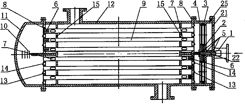
[0036] Built-in sliding cleaner backwash shell and tube heat exchanger, its composition includes: shell and tube heat exchanger, one end of the shell and tube heat exchanger is equipped with a backwash head 25, and the backwash head 25 includes Stepper motor 1, the rotary valve plate 3 installed on the linkage shaft 15 of the stepper motor 1, the rotary valve plate 3 is installed in the right valve plate 2 and the left valve plate in the backwash head 4 middle. The right valve plate 2 is connected to the right head 21, the left valve plate 4 is connected to the right end plate 8, the right end plate 8 is connected to the housing 12, and the other end of the housing 12 is connected to the left end plate 8 connected, the left end plate 8 is connected with the left head 11, the left and right end plates 8 are equipped with heat exchange tubes 9, and the heat exchange tubes 9 are installed in the heat exchange tube bracket 15 at the same time. The heat exchange tube support 15 is...

Embodiment 2

[0038] In the above-mentioned built-in sliding cleaner backwashing shell and tube heat exchanger, the two ends of the heat exchange tube 9 have oval water flow holes 7, and the two holes are horizontally symmetrical, and the two ends of the heat exchange tube 9 are installed There is a built-in sliding cleaner 6, the built-in sliding cleaner 6 is equipped with an elastic fiber brush 19, the built-in sliding cleaner 6 has a cleaner scour surface 20, and the cleaner scour surface 20 has a diameter of Greater than the height of the elliptical water flow holes at both ends of the heat exchange tube, the built-in sliding cleaner 6 can only slide in the heat exchange tube.

Embodiment 3

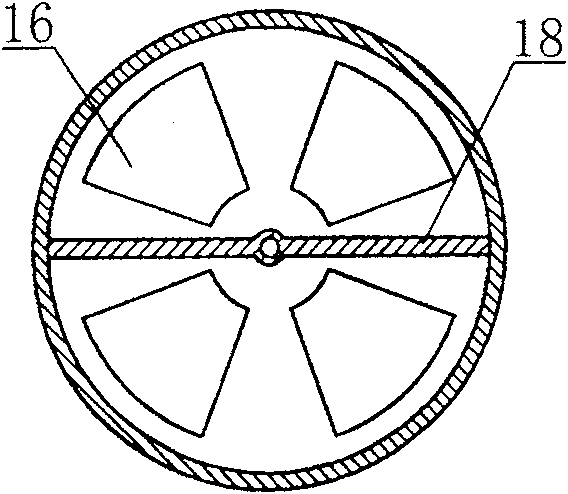
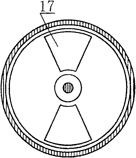
[0040] In the above-mentioned backwashing shell-and-tube heat exchanger with a built-in sliding cleaner, the left valve plate 4 has a transverse partition 18 and a static valve hole 16, and the horizontal partition 18 divides the static valve hole 16 into upper and lower groups. The right valve plate 2 has a longitudinal partition 18 and a static valve hole 16, and the vertical partition 18 divides the static valve hole 16 into two groups, the static valve hole 16 and the right valve hole on the left valve plate 4 Static valve hole 16 on the 2 is facing.


PUM


Abstract

A shell and tube type of heat exchanger with back wash by built-in slide cleaning device is prepared as setting back wash seal head on one end of tubulation heat exchanger; forming back wash seal headby stepping motor, rotary valve block set on link shaft of stepping motor, right valve block and left valve block; setting rotary valve block between right valve block and left valve block in back wash seal head.

Description

Technical field: [0001] The invention relates to a shell-and-tube heat exchanger with a built-in sliding cleaner for backwashing the internal water flow direction of the heat exchange tube, which can automatically scrub the dirt in the heat exchange tube by using the built-in sliding cleaner. technical background: [0002] The shell and tube heat exchanger is a heat exchange equipment often used in the fields of heating, air conditioning, refrigeration and chemical industry. Generally, the medium flowing in the heat exchange tube of the heat exchanger is water. Due to the presence of impurities in the water, when the water temperature When it is higher, it is also easy to scale. Therefore, after the heat exchanger runs for a long time, dirt and scale will accumulate in the heat exchanger, which not only increases the resistance of the system and equipment, increases the energy consumption of the pump, but also It increases the fouling thermal resistance of the heat exchanger...

Claims


Application Information

Patent Timeline
Patent Type & Authority Patents(China)
IPC IPC(8): F28F27/02F28G1/02F28D1/02
Inventor 张吉礼
Owner SUZHOU IBEST LOW CARBON ENERGY TECH
Learn More