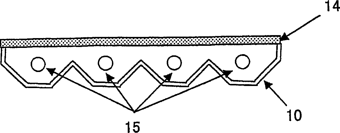
Optical reflector and surface light source device
一种光反射体、反射率的技术,应用在反射器、显示装置、照明装置等方向,能够解决面光源亮度不均等问题,达到维持画质的效果
- Summary
- Abstract
- Description
- Claims
- Application Information
AI Technical Summary
Problems solved by technology
Method used
Image
Examples
manufacture example 1
[0068] Composition (B) mixed with PP1, HDPE and filler in the amount shown in Table 2, and compositions (A) and (C) mixed with PP2 and filler in the amount shown in Table 2 were extruded by 3 machines respectively The machine melts and kneads at 250°C. Then, these kneaded products are supplied to a co-extrusion die, and after the protective layers (A) and (C) are laminated on both surfaces of the base layer (B) in the die, they are extruded in sheet form, and cooled The rolls were cooled to about 60°C to obtain a laminate.
[0069] After reheating the laminate to 145°C, stretch it in the longitudinal direction at the magnification shown in Table 2 by using the difference in linear speed of a plurality of roll groups, and then reheat to 150°C, and stretch it in the width direction with a tenter. stretched at the ratios shown in Table 2. Next, after performing annealing at 160° C., it was cooled to 60° C. with a cooling roll, and the burrs were cut off to obtain a white polyol...
manufacture example 2
[0071] The composition (B) which mixed the PP1, HDPE, and filler in the quantity shown in Table 2 was melt-kneaded at 250 degreeC with the extruder. Then, it extruded in sheet form, and cooled to about 60 degreeC with the cooling roll, and obtained the base material layer (B). After reheating this base material layer (B) to 145 degreeC, it stretched by the ratio shown in Table 2 in the longitudinal direction by utilizing the linear velocity difference of several roll groups.
[0072]Compositions (A) and (C) in which PP2 and fillers were mixed in the amounts shown in Table 2 were melt-kneaded, melt-extruded on both sides of the obtained substrate layer (B), and the protective layer (A) was laminated. , (C). Next, this laminate was heated again to 160° C., and stretched at the magnification shown in Table 2 in the width direction by a tenter. Then, after performing annealing at 160° C., it was cooled to 60° C., and the burrs were cut off to obtain a white polyolefin film havin...
manufacture example 3
[0074] The composition (B) in which PP1 and filler were mixed in the amount shown in Table 2, and the compositions (A) and (C) in which PP2 and filler were mixed in the amount shown in Table 2 were respectively extruded with three extruders. Melting and kneading at 250°C. Then, these kneaded products are supplied to a co-extrusion die, and after the protective layers (A) and (C) are laminated on both surfaces of the base layer (B) in the die, they are extruded in sheet form, and cooled The rolls were cooled to about 60°C to obtain a laminate.
[0075] After reheating the laminate to 145°C, stretch it in the longitudinal direction at the magnification shown in Table 2 by using the difference in linear speed of a plurality of roll groups, and then reheat to 150°C, and stretch it in the width direction with a tenter. stretched at the ratios shown in Table 2. Next, after performing annealing at 160° C., it was cooled to 60° C., and the burrs were cut off to obtain a white polyol...
PUM
| Property | Measurement | Unit |
|---|---|---|
| particle diameter | aaaaa | aaaaa |
| porosity | aaaaa | aaaaa |
| glass transition temperature | aaaaa | aaaaa |
Abstract
Description
Claims
Application Information
 - R&D
- Intellectual Property
- Life Sciences
- Materials
- Tech Scout
- Unparalleled Data Quality
- Higher Quality Content
- 60% Fewer Hallucinations
Browse by: Latest US Patents, China's latest patents, Technical Efficacy Thesaurus, Application Domain, Technology Topic, Popular Technical Reports.
© 2025 PatSnap. All rights reserved.Legal|Privacy policy|Modern Slavery Act Transparency Statement|Sitemap|About US| Contact US: help@patsnap.com


