Multiple channel micro-flow control chip, process for making same and use thereof
A microfluidic chip and multi-channel technology, applied in the direction of material inspection products, biological testing, material electrochemical variables, etc., can solve the problems that the advantages of electrochemical detection have not been fully utilized, and the limitations of single channels have not been broken through, so as to avoid High cost and interference problems, low cost, wide and deep channel effect
- Summary
- Abstract
- Description
- Claims
- Application Information
AI Technical Summary
Problems solved by technology
Method used
Image
Examples
Embodiment 1
[0051] The making of embodiment 1 A sheet
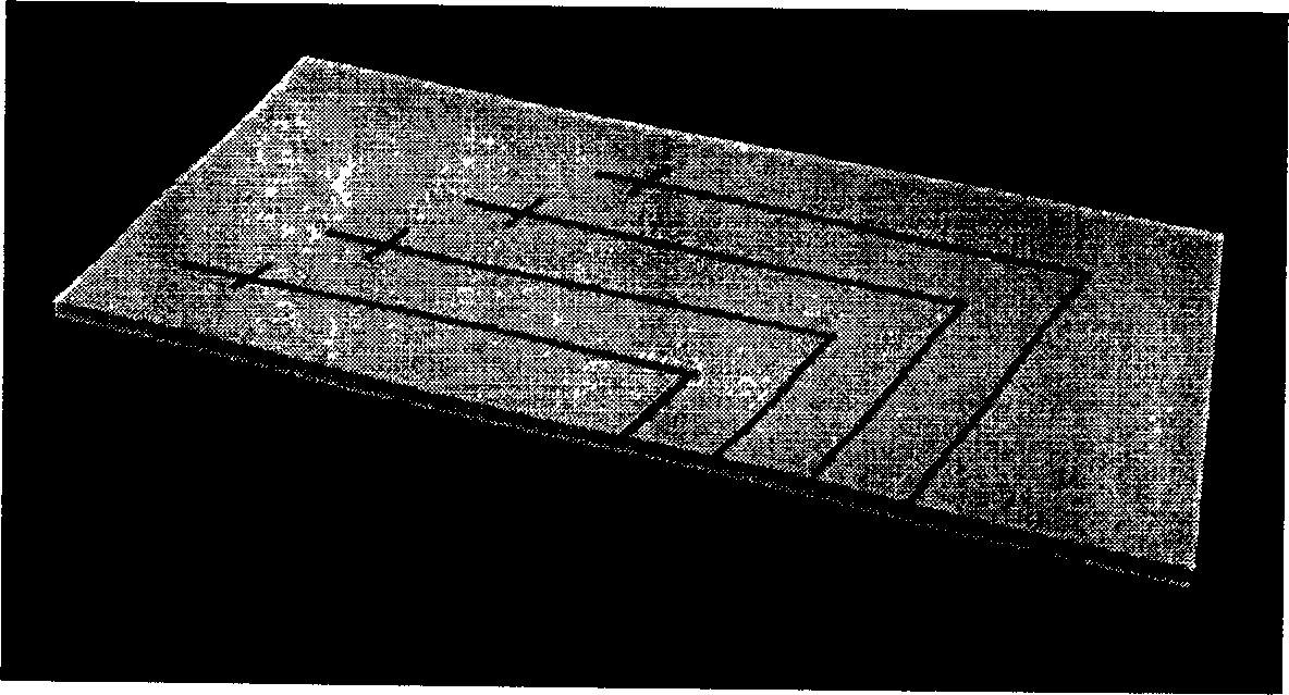
[0052] Sheet A is the substrate, and its production includes the production of the monocrystalline silicon positive mold, the separation and injection microchannel, and the working electrode. The specific production process is as follows:
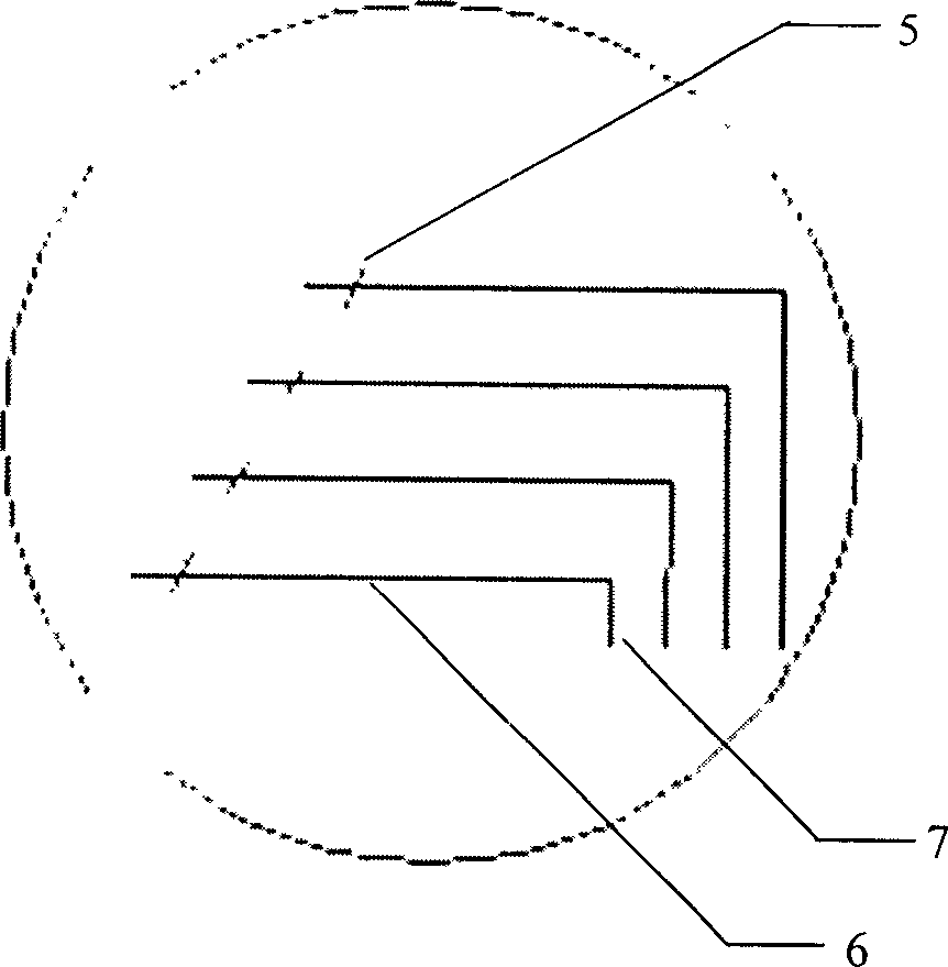
[0053] (1) Mask production: drawing by CAD software figure 1 As shown in the design drawing, the length of the sampling channel (referring to the distance between the sample pool and the edge of the waste pool) is 2.828mm, the lengths of the four working electrode channels are 7, 13, 19, and 25mm respectively, and the distance between two adjacent working electrodes The horizontal distance between them is 6mm, the length of the separation channel is 50mm, the distance between the intersection point of the injection channel and the separation channel is 45mm from the right end of the separation channel, the vertical distance between two adjacent separation channels is 7mm, and the line width of al...
Embodiment 2
[0059] The making of embodiment 2 B sheet
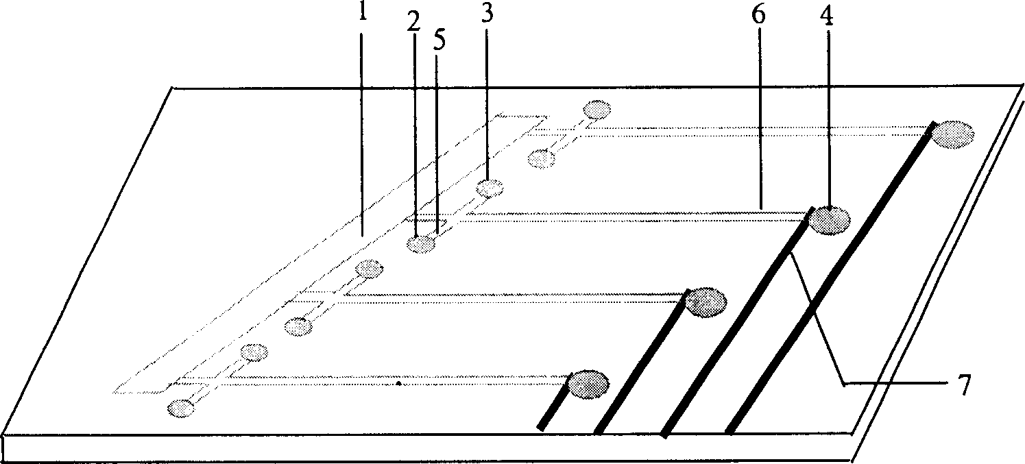
[0060] Sheet B is a cover sheet, and its structure includes various reservoir holes, including 1 buffer pool, 4 sample pools, 4 waste liquid pools and 4 independent electrochemical detection pools. The specific production process is:
[0061] (1) The size of sheet B is 4.0×8.0 cm, and the thickness is 1-3 mm. In this embodiment, PMMA with a thickness of 2 mm is selected. The coverslip was washed with distilled water, soaked in 0.1mol / L NaOH solution for 30min, washed with distilled water and dried with nitrogen.
[0062] (2) Fabrication of the buffer pool: the cross section of the buffer pool is a parallelogram with a width of 5 mm and a length of 34 mm, and the angle between the length and width is 45 degrees. Since the requirement for the size of the buffer pool is not particularly precise, it is sufficient to use a diamond drill to drill holes in this embodiment. The height of the buffer pool is the thickness of slice B, ie 2mm...
Embodiment 3
[0064] Embodiment 3 The sealing of sheet A and sheet B and the making of electrodes
[0065] Use hot pressing method to seal A piece and B piece. The specific production process is:
[0066] (1) Ultrasonic cleaning of slices A and B, and air-dried.
[0067] (2) Align slice A and slice B accurately under the microscope so that the distance between the working electrode and the edge of the reservoir is about 30 μm. After aligning the position, fix and clamp the substrate and the cover with two pieces of glass and put them into the oven, program the temperature to 108°C, keep it warm for 2 minutes, and then program to cool down to 45°C.
[0068](3) Production of each electrode: the electrode used to provide high voltage in the buffer pool 1 is a Pt wire with a length of 10 mm and a diameter of 0.5 mm; the electrodes of the sample pool 2 and the waste liquid pool 3 are 5 mm long and 0.5 mm in diameter The detection cell 4 is a three-electrode working system, and the working ele...
PUM
| Property | Measurement | Unit |
|---|---|---|
| height | aaaaa | aaaaa |
| width | aaaaa | aaaaa |
| length | aaaaa | aaaaa |
Abstract
Description
Claims
Application Information
 - R&D
- Intellectual Property
- Life Sciences
- Materials
- Tech Scout
- Unparalleled Data Quality
- Higher Quality Content
- 60% Fewer Hallucinations
Browse by: Latest US Patents, China's latest patents, Technical Efficacy Thesaurus, Application Domain, Technology Topic, Popular Technical Reports.
© 2025 PatSnap. All rights reserved.Legal|Privacy policy|Modern Slavery Act Transparency Statement|Sitemap|About US| Contact US: help@patsnap.com


