
Testing apparatus and testing method for printable property of soldering paste

A test device and printability technology, applied in the direction of measuring devices, mechanical devices, instruments, etc., can solve the problems of rough measurement methods, low precision, and reduced solder paste rolling ability, and achieve the effect of fast printability of solder paste

Inactive Publication Date: 2005-09-28
吴懿平
View PDF2 Cites 1 Cited by
  • Summary
  • Abstract
  • Description
  • Claims
  • Application Information

AI Technical Summary

Problems solved by technology

[0007] ② Long-term scratching damages the spherical shape of the solder powder itself, reducing the rolling ability of the solder paste;
[0013] 1. The off-line test method cannot reflect the continuous change of solder paste printability;
[0014] 2. The measurement method of the online method is relatively rough and the accuracy is not high

Method used


Image

  • Testing apparatus and testing method for printable property of soldering paste
  • Testing apparatus and testing method for printable property of soldering paste
  • Testing apparatus and testing method for printable property of soldering paste

Examples


Embodiment 1

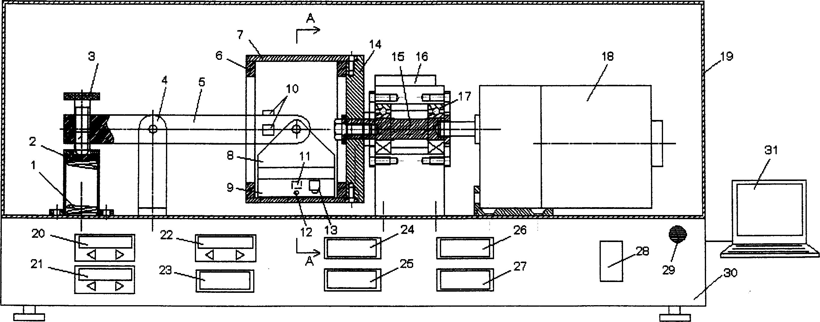
[0047] refer to figure 1 , all printing mechanisms are placed in the temperature and humidity atmosphere control box 19, by adjusting the temperature adjustment indicator 20 and the humidity adjustment indicator 21, the heater and the humidity regulator not shown in the temperature and humidity atmosphere control box 19 are controlled, Make the temperature and humidity in the temperature and humidity atmosphere control box 19 reach the set value, and can feed protective gas, such as nitrogen, into the temperature and humidity atmosphere control box 19 at the same time.

[0048] The output shaft of the decelerating DC motor 18 is rigidly connected with the mandrel 15 using a keyway, the mandrel 15 is rigidly connected with the turntable 14 with screws, the boss of the turntable 14 is embedded in the ring template 7, and the mandrel 15 is installed in the bearing 17 and can rotate. The turntable 14 and the ring template 7 are connected on the mandrel 15 to form a cantilever stru...

Embodiment 2

[0066] The rotating part of the ring template is as Figure 6 shown.

[0067] The device of embodiment 2 is different from the device of embodiment 1 except that the design of the rotating part of the ring formwork is different, and all the other functions and procedures are the same. figure 1 The positions of the console in the control box and other mechanisms and instruments in the temperature and humidity atmosphere control box are slightly changed. The rotating part of the ring formwork in this embodiment is a gear-toothed belt transmission structure. For the specific structure, see Figure 6 , the ring template outer band ring gear 33, the deceleration DC motor drives the ring template with the ring gear 33 through the mandrel 35, driving wheel 36, toothed transmission belt 34. The support wheel 37 is used to support the rotation of the ring template 33 . In addition to the advantages of Embodiment 1, this embodiment, since the ring template is not the rigid structure ...


PUM


Abstract

The present invention is soldering paste printability test apparatus and method. The test apparatus includes scraper loading part comprising spring, press rod rack, scraper holder, scraper, etc.; ring temperature rotating part comprising scraper blocking ring, ring template, turntable, spindle, DC reducing motor, etc; control and test part comprising atmosphere temperature and humidity controlling box, micro strain sheet, micro mechanical sensor, video camera, etc; and computer as the peripheral equipment. The test method includes using printing unit of scraper-ring structure in printing soldering paste continuously in different temperature and humidity, and monitoring soldering paste rolling state change with video camera, micro strain sheet and micro mechanical sensor to evaluate the printability of soldering paste.

Description

technical field [0001] The invention relates to a device and method for testing the printability of solder paste, which is specially used for measuring the printing performance of solder paste and other materials printed by stencil printing or screen printing, such as conductive glue and printing ink. Background technique [0002] So far, in the assembly and production of electronic boards, the most commonly used is surface mount technology. It uses solder paste as the connection material, applies the solder paste to the pads to be soldered on the printed circuit board by stencil printing or drip coating, and then mounts the components, and finally the soldered parts can be obtained through the reflow process. board. [0003] Since the stencil printing process of solder paste is very simple and has high production efficiency, it has become a mainstream technology. The specific method is: first place the flat template with the leakage hole on the pr...

Claims


Application Information

Patent Timeline
Patent Type & Authority Applications(China)
IPC IPC(8): G01N19/04G01N21/84
Inventor 吴懿平安兵汪洪生吴丰顺王磊
Owner 吴懿平
Learn More