
Bonded substrate, surface acoustic wave chip, and surface acoustic wave device

A surface acoustic wave and substrate technology, which is applied in the direction of device material selection, piezoelectric devices/electrostrictive devices, piezoelectric/electrostrictive/magnetostrictive devices, etc., can solve the problems of reduced device qualification rate and reduced joint strength

Active Publication Date: 2005-09-07
TAIYO YUDEN KK
View PDF2 Cites 19 Cited by
  • Summary
  • Abstract
  • Description
  • Claims
  • Application Information

AI Technical Summary

Problems solved by technology

Here, this will cause problems of reduced joint strength and reduced device yield

Method used


Image

  • Bonded substrate, surface acoustic wave chip, and surface acoustic wave device
  • Bonded substrate, surface acoustic wave chip, and surface acoustic wave device
  • Bonded substrate, surface acoustic wave chip, and surface acoustic wave device

Examples


Embodiment Construction

[0021] Embodiments of the present invention will be described below with reference to the drawings.

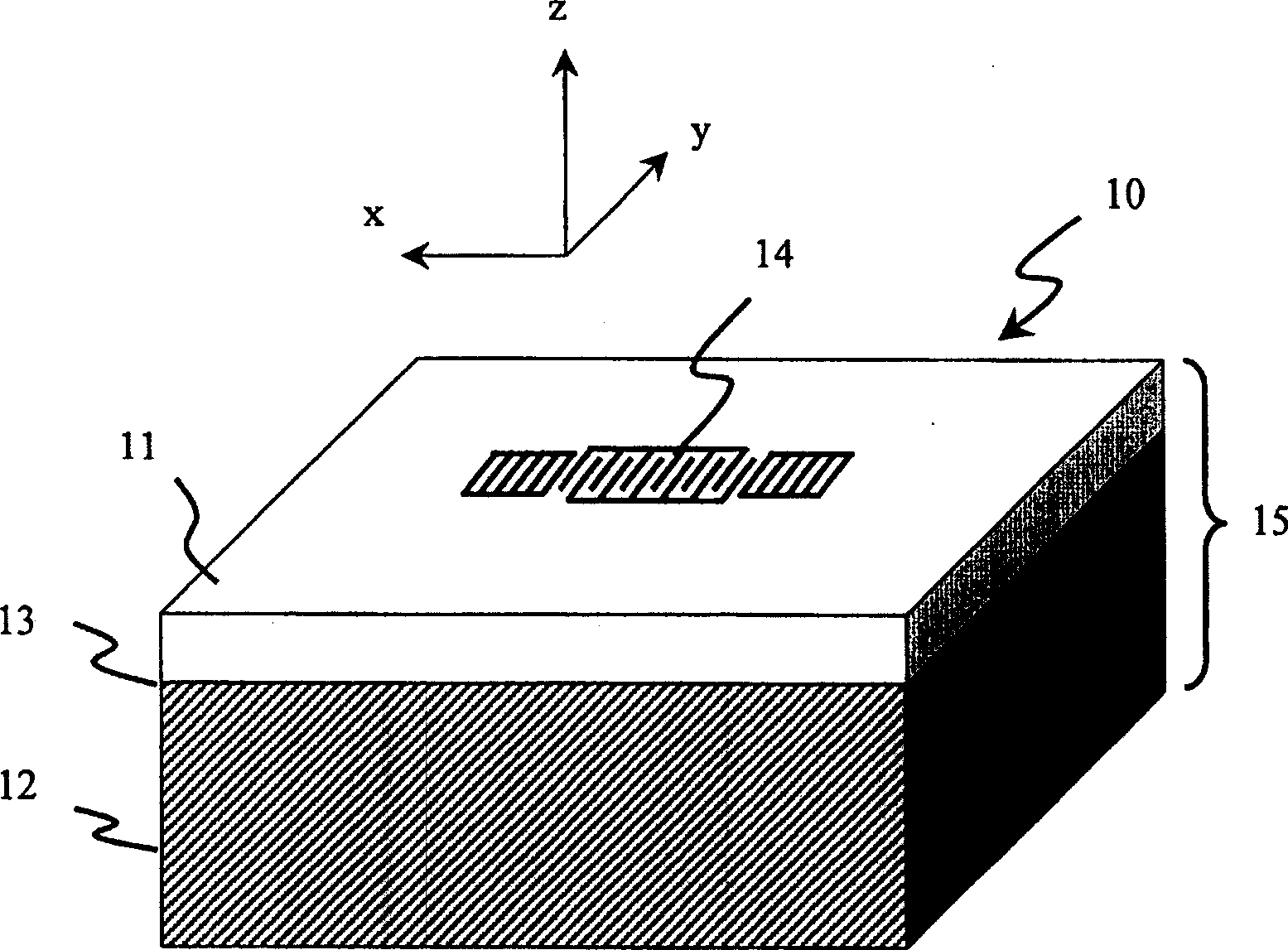
[0022] figure 1 is a perspective view of a SAW chip manufactured using the bonded substrate according to the present invention. The SAW chip 10 includes a bonding substrate 15 . The bonding substrate 15 includes a piezoelectric substrate 11, a supporting substrate 12, and a bonding interface 13 in an amorphous state. The piezoelectric substrate 11 and the support substrate 12 are bonded via a bonding interface 13 . The SAW resonator 14 is placed on the main surface of the piezoelectric substrate 11 so that the SAW propagates in the X direction.

[0023] The piezoelectric substrate 11 employs a single crystal LT substrate (42° Y-cut X-propagation LT substrate) that is rotated at 42 degrees around the X axis as the propagation direction and Y-cut. The single crystal LT substrate has a thickness of 40 μm. The linear expansion coefficient of the SAW propagation direction X of...


PUM


Abstract

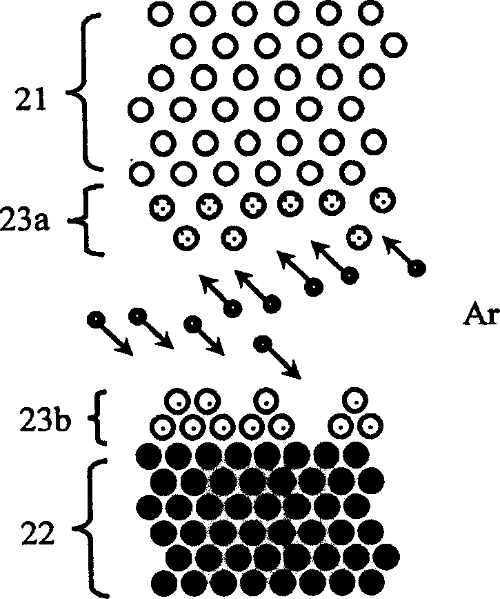
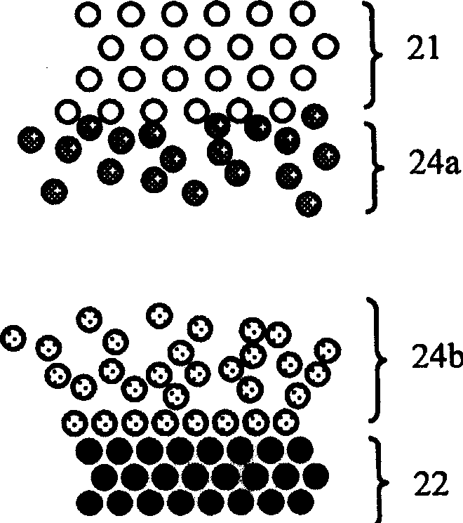
A bonded substrate includes a lithium tantalate substrate and a sapphire substrate to which the lithium tantalate substrate is bonded, a bonded interface of the lithium tantalate and the sapphire substrate includes a bonded region in an amorphous state having a thickness of 0.3 nm to 2.5 nm. The bonded region in the amorphous state is formed by activating at least one of the lithium tantalate substrate and the sapphire substrate in the bonded interface with neutralized atom beams, ion beams or plasma of inert gas or oxygen. It is possible to bond the piezoelectric substrate to the supporting substrate having different lattice constants without the high-temperature thermal treatment and realize the bonded substrate having an excellent bonding strength and being less warped.

Description

technical field [0001] The present invention generally relates to a bonded substrate and a surface acoustic wave chip, and more particularly, to a substrate in which a lithium tantalate substrate and a sapphire substrate are bonded together, and a surface acoustic wave chip equipped with the bonded substrate. Background technique [0002] A surface acoustic wave (hereinafter referred to as SAW) device is fabricated using a piezoelectric substrate having a plurality of comb electrodes thereon. High-frequency power is applied to one comb-shaped electrode to generate a surface acoustic wave, which is converted into a high-frequency signal by the other comb-shaped electrode. [0003] The wavelength of SAW devices is 10 times smaller than that of electromagnetic waves -5 . Therefore, the SAW device can be miniaturized. SAW devices have high propagation efficiency due to their low loss. In addition, the technology of the semiconductor manufacturing process can be used to produ...

Claims


Application Information

Patent Timeline
Patent Type & Authority Applications(China)
IPC IPC(8): H01L41/09H01L41/18H01L41/22H01L41/23H01L41/312H03H9/02H03H9/25
CPCH03H9/02559H03H9/02574H10N30/072H03H9/25H03H9/145H03H9/64
Inventor 三浦道雄上田政则相川俊一上村亨和田一久三岛直之
Owner TAIYO YUDEN KK
Learn More